


The following procedure describes the steps to define a SMART Crack Growth object. The procedure assumes that you have already inserted a Fracture folder and defined the prerequisite crack. This crack can be any of the supported crack types. The feature supports the definition of multiple SMART Crack Growth objects when your model contains multiple cracks.
Insert a SMART Crack Growth object into the Outline by right-clicking on the Fracture object and selecting > from the context menu. Alternatively, you can select the option on the Fracture Context Tab or right-click in the Geometry window and select > . Once inserted, the Initial Crack and Material properties highlight.
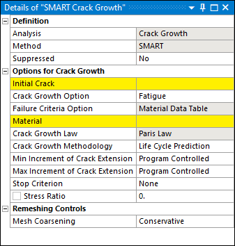
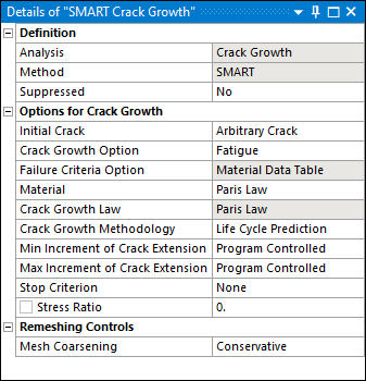
Select the crack or Crack Initiation object that you have already created from the drop-down list of the Initial Crack property. An Arbitrary Crack has been selected in the following example. Once selected, the application automatically assigns the Material of the object specified by the Initial Crack property.
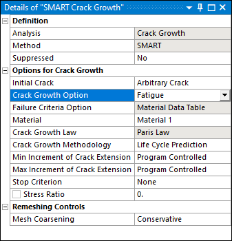
Specify the Crack Growth Option property. The setting of this property is based on the desired type of crack growth propagation. Select Fatigue (default) or Static.
- Fatigue
If you set the Crack Growth Option property to , your structure is subject to constant amplitude cyclic load.
The following other properties are available in the category:
Failure Criteria Option: This is a read-only property that is set to .
Material: The application uses the material that is assigned to the geometry used to define the crack selected in the Initial Crack property. You can change the material using the property's fly-out menu.
Requirement: This material must include the material property Paris’ Law.
Crack Growth Law: This is a read-only property that displays the given Crack Growth Law: .
Crack Growth Methodology: Fatigue crack growth can be modeled using either (default) or methodologies. If you specify Cycle By Cycle, the property Incremental Number of Cycles displays. Use this property to specify the incremental number of cycles during a substep. The default setting is
10.The following additional properties are also available:
Min Increment of Crack Extension: This property specifies the minimum crack extension increment value. The options include (default) and . The option uses the default minimum increment value. If you set the property to , The Min Increment Value property displays and enables you to specify a value. The default value is
0.Max Increment of Crack Extension: This property specifies the maximum crack extension increment value. The options include (default) and . The option uses the default maximum increment value. If you set the property to , The Max Increment Value property displays and enables you to specify a value. The default value is
0.Stress Ratio: You use this property to specify the stress ratio. The default value is
0. The entry range is less than1.
- Static
If you set the Crack Growth Option property to , crack growth modeling is based on selected fracture parameters and criteria.
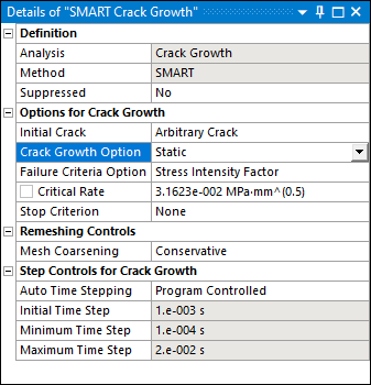
Using the Failure Criteria Option property, you can specify the failure criteria as either (default) or . Each option requires you to specify a value in the dependent property Critical Rate. The default value for the Critical Rate property is
0for either option. The unit system of the Critical Rate property varies based on your selection. The property can be parameterized.Note: Either the or fracture parameter can be computed in one solution. Additionally, you can compute Equivalent SIFS Range fracture result and related time history results on any crack front node (Fracture Probes).
Furthermore, when you set the Crack Growth Option property to , an additional category displays for the object: Step Controls for Crack Growth. The properties for this category include:
Auto Time Stepping: Property options include (default) or . Setting the property to Manual enables you to modify the following time step properties, otherwise they are read-only.
Initial Time Step: Defines the initial time step to initiate crack growth.
Minimum Time Step: Minimum time step for subsequent crack growth.
Maximum Time Step: Maximum time step for subsequent crack growth.
As needed, specify the Stop Criterion property. Options include (default), , , , and (displayed when the Crack Growth Option property is set to ).
When you select the , , or the , the --Stop Value property displays. This property requires you to enter a value for the selected Stop Criterion option. Once the maximum stop criterion limit is reached, the application stops the solution process. In this instance, the solution is incomplete and the Solution folder will not be in solved state because the solution is not complete for all time points. If the maximum stop criterion limit is not reached during solution, then the solution process completes normally.
Specify the Mesh Coarsening property. You use this property to define a desired level of coarsening of the excessively fine mesh surrounding the crack front during the SMART crack growth remeshing processing. Options include:
(default): This option performs the least amount of mesh coarsening and creates a larger number of nodes and elements after a substantial amount of crack-growth. This options offers the greatest remeshing success rate.
: This option modestly reduces the number of nodes and elements and offers a satisfactory remeshing success rate.
: This option quickly coarsens the mesh in the region behind crack front and offers the largest reduction in the number of nodes and elements following a substantial amount of crack-growth.
Repeat the steps above to define additional SMART Crack Growth objects when multiple cracks exist in the model.