Remember the following notes when using the Sizing control:
Visual aids are available to assist you. When you pick an edge, the edge length is displayed. A circle is displayed adjacent to the cursor whose diameter indicates the current setting in the Element Size field. The scale ruler is displayed below the graphic and provides a good estimate of the scale of the model. Also for edge sizing, if you specify a bias, and if you set Element Size to a value other than Default, the size control will be displayed graphically with the initial mesh density (including any specified bias) in the Geometry window.
When Applying Sizes to Faces: Faces adjacent to a face that has a scoped size control applied to it respect the source as part of the sizing control. Meshes on the adjacent faces will transition smoothly to the size on the scoped face. When size controls that have differing sizes are on adjacent entities, the adjacent topology receives the smallest size.
When Applying Sizes to Edges: If possible, the meshing algorithm places the requested number of divisions on the specified edge. Otherwise, the algorithm adjusts the number to allow a successful mesh generation. When Behavior is set to Hard, the number of divisions is given a higher priority and the mesher may fail rather than adjust the number of divisions. In case of failure, inspect the messages for more information as to what constraints may be causing it.
Note:In MultiZone, a closed edge is represented by more than one blocking topological edges. Therefore, user-specified edge node distribution size may not be respected. However, the number of intervals will still be respected.
For split curves in rotated edge association, only interval count, not distribution, will be respected.
When Sweeping: Consider the following when applying size controls to source and target geometry:
If your sizing controls are scoped to either the source or target face, the mesher will transfer the size control to the opposite face. If you have a size control on both faces, the size on one of the faces will be used. That face is automatically determined by the software. However the size on the edges of the target face will not be affected if no sizes are explicitly defined on these edges.
Edge sizing applied to a target face is respected only if Behavior is .
If you have a sphere of influence on a possible source or target face, the face with the most spheres will be chosen as the source face. The edge mesh of the source face affected by the sphere of influence will not affect the target face. This may prevent the model from sweeping with acceptable element quality. To avoid this, place the sphere of influence on the edges of both the source and target face.
Applying sizes, regardless of type (that is, size, number of divisions, sphere of influence), to the edges of possible source and target faces will only affect the faces that use these edges.
If you want to control a side area, the problem must be properly constrained such that the interval assignment does not override your size control. The divisions on the edge may decrease in order to make the body sweepable. When using a meshing process other than swept meshing, the divisions can only increase. When applying a size to a part that is sweepable, the resulting mesh may have fewer divisions on the edge than specified due to the interval assignment logic of the sweepers.
When sweeping a model, if you use the sizing control and the sphere is not touching the edges of a side area or is totally enclosed in the body, the sphere will have no effect.
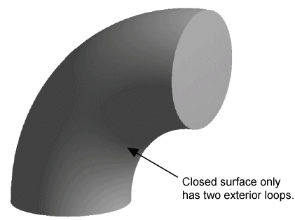
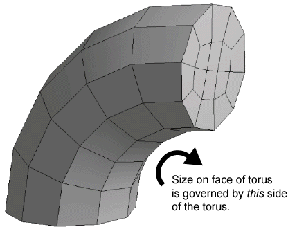
When sweeping a closed torus (shown below) with an applied size on the face of the torus, the number of divisions that will result on the torus is governed by the arc length between the caps of the surface on the inside of the torus.
Using the sizing control may not have any effect on the generated mesh if the control is scoped to the Body of a Line Body.
In general, users are discouraged from defining a body of influence and a sphere of influence such that the regions of influence overlap. In cases where elements fall within overlapping bodies/spheres of influence, elements will be created using the sizing that appears lowest in the Tree.
Regardless of the value for the sizing control you set, other factors such as edge and face curvature and the proximity of small features may override the effect of the sizing control.
When using mapped face controls, or Sweep or MultiZone parallel edge assignments are handled automatically for mapped faces. That is, for a mapped face, there are two sets of parallel edges. If you increase or decrease the sizing on one edge, the same increase or decrease occurs automatically on the other edge to ensure a mapped mesh is possible. If a model contains a row of mapped faces (such as the sides of a box), you can set a number of elements on one edge and the same number of elements will be forced on all side/parallel edges. Setting Behavior to Hard will give that edge priority. In case of conflict between two edges that should be parallel but have different hard sizing controls assigned to them, the software will either fail and print a message about the conflict, or a free mesh will be given for that face.
When using MultiZone:
If you scope bias settings to parallel edges, and the sizings create conflicts, they are applied according to the following priority:
Double bias edge (highest priority)
Single bias edge
No bias edge
Setting Behavior to Hard on an edge gives that edge a higher priority. That is, a hard edge sizing takes priority over a soft edge sizing, but among sizing controls that are hard or soft, the order of priority is double, single, then no biasing.
If you apply a local Sizing control to a solid body with a Method control set to Hex Dominant or Sweep, or to a sheet body with a Method control set to Quadrilateral Dominant, a near uniform quadrilateral mesh will result on all affected faces on a body meshed with Hex Dominant, on the source face meshed with Sweep, and on all affected faces meshed with Quadrilateral Dominant. To obtain even more of a uniform quadrilateral mesh, set the Behavior of the Sizing control to Hard.
If several sizing controls are attached to the same edge, face, or body, the last control is applied. If a sizing control is placed on an edge and then another is placed on a face or body that contains that edge, the edge sizing takes precedence over the face or part sizing.
If you have adjusted the element size, then changed length units in a CATIA or ACIS model, when you choose Update or Clear Generated Data at a Model or Project node in the Tree Outline, you may need to re-adjust the element size. The sizing control does not automatically re-adjust to match this situation.
When using MultiZone Quad/Tri and Surface Mesh Method is set to Uniform, the Element Size will take priority over local face or body sizings unless the specified face or body size is smaller than the Element Size. This means you can use face or body sizing to obtain a finer mesh, but not to obtain a coarser mesh.
For a table summarizing the behaviors of local sizing controls when used with various mesh methods, refer to Interactions Between Mesh Methods and Mesh Controls.


