The is used to create Winding Bodies (a special form of line body) that represent coils of wire wound through slots of a rotor or stator of a motor. The Winding Bodies generated will automatically be named using the phase and coil from the Winding Table.
When you select a winding body, you will be shown the cross section size for the coil and the number of turns for it. Unlike standard Line Bodies, you cannot change the Cross Section or Alignment of its edges. The itself sets these. Like normal Line Bodies, the display of Winding Bodies is affected by the View options Cross Section Alignments, and Cross Section Solids.
Winding Tool topics:
Interface
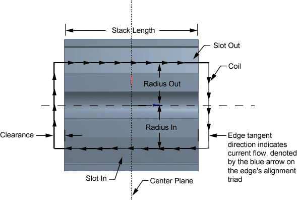
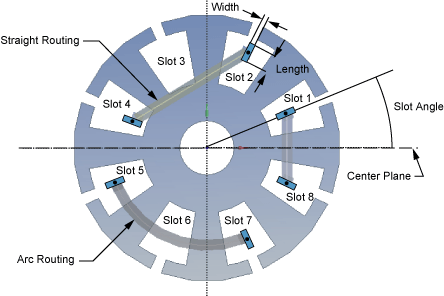
Before selecting Winding Table from the Tools Menu , you should first create a model of the rotor or stator to which it will be applied, and the center plane that will define the alignment of the Winding Bodies. Below are two diagrams showing how the winding coils are defined.
Below are the properties required to define the Winding feature:
Center Plane: A plane defined midway between the ends of the rotor or stator, with its origin and Z-axis at the center of the rotor or stator. It is recommended that you create this plane prior to creating the Winding feature.
Winding Table File: This is where you pick the Winding Table File to use. When this is set/changed, it is read and the value in the next property, "Number of Slots" is set from it. Also if the Winding Table is displayed, you will be able to see what was read from the file. A Winding Table File is not required. You may enter the winding data manually.
Number of Slots: This is used to compute the location of all the other slots. This value must be the same as that in the Winding Table. This value is initially 0, so the property shows as "Invalid". A value greater than 1 must be entered. If you enter a Winding Table File, this value is set from the "SLOTS n" record in that file. If this value is changed, it resets all slot angles to be equally spaced around a full circle (see Slot Angles below).
Stack Length: This is the distance between the ends of the rotor or stator. The actual length of the coil edges that go through a slot will be this length plus the clearance value added at each end.
Slot Angle: This is the counterclockwise (CCW) angle from the X-axis of the Center Plane to a radius line from the origin of the Center Plane through the center of Slot 1. If there is a Skew Angle, it is important to understand that this value is measured at the central plane. (For the angle of other slots, see Slot Angles.)
Skew Angle: If this is zero, the coils will go in a direction normal to the central plane as they pass through the In and Out slots. If it is not zero, the location at the top and bottom of the rotor or stator will be modified by half the Skew Angle, counterclockwise at the top and clockwise (CW) at the bottom. In fact, the top and bottom of the coil will be modified slightly more than that as the angle continues to "skew" the Clearance distance beyond the top and bottom of the rotor or stator. The skew angle must be in the range from -12.0 to 12.0 degrees.
View Winding Table: The default for this is Yes, which means you want to display the Winding Table and allow it to be edited via the Winding Table Editor.
Refresh: This is automatically set to Yes when you change the Winding Table File, or the Number of Slots (since that must agree with the value in the Winding Table). When this value is Yes, then the Winding Table File will be parsed for its values when the feature is generated.
Clash Detection: When this is set to Yes and Solid bodies are selected in the next property, then Clash Detection will be performed during Generate. The SlotIn portion of each coil will be tested for clashes with the selected bodies. If the radius for the SlotOut is different than that for the SlotIn, then the SlotOut portion of the coil will also be tested for clashes. If no body is selected, or this property is set to no, then no clash detection is done for the coils. However, you will still be warned of a possible clash at the ends if the clearance for a coil is not larger than half of the width specified for that coil. Clashes between coils are not looked for.
Body for Clash Detection: This property is only seen if the previous property is set to Yes. This allows the selection of bodies for the clash detection. If the previous property is set to Yes and no Solid bodies are selected, this property will show as Invalid, and a warning will be issued for the feature during Generate.
As with other features, the Winding Bodies are not actually created, or the Winding Table parsed until you select Generate.
Note that standard Cross Sections as created under the Concept Menu are not used for Winding bodies. Instead, the cross section information for a Winding Body is provided in the Winding Table for each coil. These values are used in a similar way to standard Cross Sections.
When the Ansys DesignModeler parts are transferred to the Mechanical application, information is sent to the Mechanical application identifying the Winding Bodies, along with the Number of Turns and the special cross section information needed.
Winding Table
To create winding bodies, you will need a Winding Table to provide information needed for each coil. The Winding Table is a ".txt" file with the following characteristics:
After a pound sign '#', everything else on that line is considered a comment and is ignored.
Empty lines are ignored.
Values on a line are separated by spaces and/or tabs.
Keywords are not case sensitive. Version, version, VERSION, VeRsIoN are all valid.
At the top of the file are two special lines:
VERSION 10.0 SLOTS 8 The primary data lines must contain the following columns, in order, left to right:
Phase Coil Turns SlotIn SlotOut Routing Clearance RadiusIn Radius-Out CSType Length Width Rotate Ends Phase is a text string with no spaces/tabs in it. It is limited to 20 characters. The phase and coil are used to maintain persistence for the winding bodies. If you modify the phases or coils, it is possible that other features dependent on this feature may not generate successfully.
Coil, Turns, SlotIn, and SlotOut are integer values greater than zero.
SlotIn and SlotOut must be different and not greater than the number of slots.
A data line with the same Phase and Coil of a previous line is an error.
Routing must be STRAIGHT or ARC (or 0/1). This is how the connections between slots are made.
Clearance is the distance above and below the 'Stack Length' (see below) for the connections.
RadiusIn and RadiusOut are the radius values to the center of the cross section within a slot.
CSType must be RECT. Currently this is the only value allowed here.
Length is the size of the cross section in the direction of a radius from the axis through the slot.
Half the width must be smaller than the clearance or you will get a warning of a possible clash between the connection and the end of the rotor/stator.
Rotate Ends is an optional column with values of Yes/No (1/0 are also accepted). If Yes (or 1), this will rotate the alignment of the connections between slots by 90°. This can be useful for coils that connect slots on opposite sides of the winding (near 180° apart).
Sample Winding Table File
VERSION 10.0
SLOTS 8
#Sample Winding Table with 8 slots
#Format is: (shown here as two separate groups of information)
| #Phase | Coil | Turns | SlotIn | SlotOut | Routing | Clearance |
| A | 1 | 50 | 6 | 1 | Straight | 0.6 |
| A | 2 | 50 | 7 | 2 | Straight | 0.6 |
| A | 3 | 50 | 8 | 3 | Straight | 0.6 |
| B | 1 | 50 | 5 | 2 | Straight | 0.76 |
| B | 2 | 50 | 6 | 3 | Straight | 0.76 |
| B | 3 | 50 | 7 | 4 | Straight | 0.76 |
| RadiusIn | RadiusOut | CSType | Length | Width | Rotate Ends |
| 8.0 | 8.0 | RECT | 2.0 | 1.0 | Yes |
| 8.0 | 8.0 | RECT | 2.0 | 1.0 | Yes |
| 8.0 | 9.0 | RECT | 2.0 | 1.0 | Yes |
| 9.0 | 9.0 | 50 | 2.5 | 1.5 | No |
| 9.0 | 9.0 | RECT | 2.5 | 1.5 | No |
| 9.0 | 8.0 | RECT | 2.5 | 1.5 | No |
Winding Table Editor
When the View Winding Table property is set to Yes (default), the Winding Table Editor panel will be displayed when creating and editing a Winding Tool feature, and whenever a Winding Tool feature in the Tree Outline is selected. It displays in a portion of the area where the graphics normally appears, similar to the panel for the Parameter Manager. There are two tabbed windows:
Winding Data
Slot Data
At the top will be the name of the Winding Tool, and the filename (and path) of the Winding Table File (if it has been given). At the bottom of the panel are four buttons:
Gives you the option to clear the Winding Table, and the filename if it exists.
Allows you to save the Winding Table to a file.
Gives you the option to reload the table back from an already assigned file. If no filename has been provided, this does nothing.
Allows you to close the Winding Table Editor. If you have made changes, you are given the option of saving first. You can then turn it back on via the View Winding Table property.
Winding Data
In between the names at the top and the buttons at the bottom, the information in the Winding Table is displayed in columns corresponding to the columns described in the section Winding Table File. You will note that comments (phase name starting with a "#") are displayed in green and invalid values are displayed in red. If the file was read from an external file and there was missing data, those positions display as three consecutive question marks (???). If you right click on a row in the table, you are given several options:
Inserts a row in front of the current row.
Deletes a row in front of the current row.
Cuts a row in front of the current row.
Copies a row in front of the current row.
Only offered if a row has been Cut or Copied, puts pasted row in front of current row.
To insert a row at the end, just click in the Phase cell of the row after the last one in the table. Once you have entered the Phase cell, the rest of the row is able to be edited, unless you entered a comment ("#" at start of the phase). You will note that when new rows are inserted, or added at the end, an attempt is made to set default values based on the values in neighboring rows.
Slot Angles
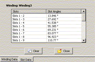
By default, the slot angles are equally spaced in a full circle, with the spacing based on dividing 360 by the number of slots. Anytime you change the number of slots, this spacing is adjusted based on the above formula, and any custom angles you have entered are lost. If you want to change the angles, then when the Winding Table is being displayed via View Winding Table, you can click on the Slot Data tab to view the slot angles.
Here, you will see the angle of each slot, as measured from the first slot (S1). This way, if you change the Slot Angle property, all the other slots will rotate with it. All slot angles must be greater than 0.0° and less than 360.0°.
Also, to preserve the numbering order, slot angles must always be greater than the previous slot angle and less than the following slot angle. Angles entered that do not meet these requirements will not be accepted.
Finally, remember that anytime you change the number of slots, or click on the Clear button here, the values in this table will revert to equal spacing around a circle.


