


You can use the Grille feature to create the Grille geometry for export to Ansys Icepak. You need to specify bodies created by the Opening feature as input to the Grille feature. All opening bodies are required to be in the same plane. This feature supports the creation of Rectangular (Axis Aligned Rectangle), Circular (Circle), Polygonal (Planar 2D Polygon), Inclined Rectangle (Axis Aligned Inclined Rectangle) and CAD (faceted or tessellated representation) shapes of Grilles.
You need to specify Opening bodies as input to the Grille feature for creating the Rectangular, Circular, Polygonal and Inclined Rectangle shapes. All opening bodies are required to be in the same plane.
To create a Polygonal grille you need to additionally provide a sketch that represents the Grille geometry. The sketch should contain only one closed chain of lines (polygon). The sketch should also be constructed in the same plane as the opening bodies.
You can choose to either preserve the input Opening bodies by setting the Preserve Opening Bodies property to Yes. If you set this property to No, the specified Opening bodies will be deleted upon successful generation of the Grille geometry.
The CAD Grille is typically used for non-planar faces representing the Grilles. To create a CAD grille, you need to provide face(s) that represent the Grille geometry. You should select faces from a single body (solid/surface) that are adjacent to each other. Additionally, as an option, you can select a sketch to cutoff the exact Grille geometry from the set of selected faces. The sketch should contain only one closed chain of lines (polygon). Once the CAD Grille feature is generated with selected inputs, then only one valid Grille body is created. The Free Area Ratio is computed and shown in the details view, when it is other than zero. The feature name will be copied to the output grille body only on first generation.
After generation of the feature you will be able to see the Free Area Ratio computed using the inputs. The Free Area Ratio will be exported to Ansys Icepak.
Example 108: Rectangular Grille
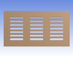 Shown above is the input face to the Opening feature. | 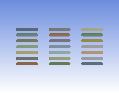 Shown above is the Opening bodies in a Rectangular arrangement. These bodies can be input to the Grille feature to create a rectangular Grille. | 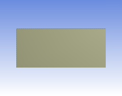 Shown above is the Rectangular body created by the Grille feature that encompasses the input bodies. |
Example 109: Circular Grille
 Shown above is the input face to the Opening feature. |  Shown above is the Opening bodies created by the Opening feature. |  Shown above is the Circular Grille body created by the Grille feature. |
Example 110: Polygonal Grille
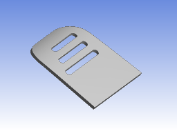
 Shown above is the input face to create the opening bodies required to create the Polygonal grille. | 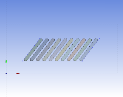 Shown above is the Polygonal sketch and the input bodies used to create a Polygonal Grille object using the grille feature. | 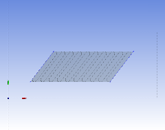 Shown above is the Grille body created by the Grille feature. |
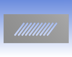
Example 111: Inclined Rectangular Grille
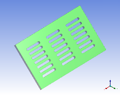 Shown above is the input face used to create the Openings for the Grille. Note that if the face is rotated about the X axis, the X axis will become parallel to the ZX plane. | 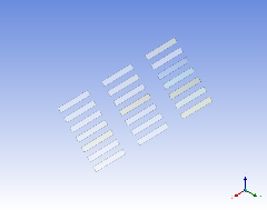 Shown above is the Opening bodies to be used as input to create the Inclined Rectangular grille. | 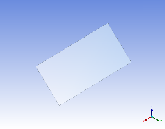 Shown above is the Inclined Rectangular body created by the Grille feature when using the input bodies shown in the previous picture. |
Example 112: CAD Grille
 Shown above is the input face to the CAD Grille feature. | 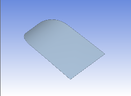 Shown above is the tessellated body created by the CAD Grille based on the input face alone. | 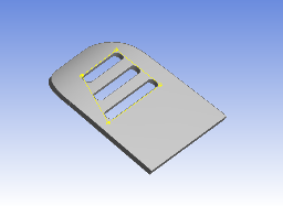 Shown above are the input face and input sketch to the CAD Grille feature. |  Shown above is the tessellated body created by the CAD Grille, based on both the input face and sketch. |
Other Electronics topics: