| Right Mouse Button Context Menu: Clear Selection, End Selection / Place offset |
The Offset function allows you to create a set of lines and arcs that are offset by an equal distance from an existing set of “straight” lines and “circular” arcs. The original set of lines and arcs must be connected in a simple end-to-end fashion and can form either an open or closed profile. You can either preselect the edges, or select them within the function and then choose the right mouse button option "End selection / Place offset" when finished with the selection process.
Now, as you move the cursor around, its location is used to determine three things:
Offset distance
Offset side
Offset area
The first two are fairly clear, but the third is also very important. If portions of your selected curves would collapse out or cross over one another given the current offset side and distance, the cursor location determines which area of offset curves is kept. With large offset distances and collapsed areas, some unique results will occur if the cursor is placed in areas that should be removed. However, by placing the cursor in desired areas, you should find that this method of allowing you to select the desired offset area allows for the offset of many very complex shapes.
Also, remember that if the offset does not give you exactly what you want, you can easily use the Trim and Extend functions to make minor changes later.
To create the new curves, click the mouse when you are satisfied with what is displayed. You can then create additional offsets, or use the right mouse button to clear the selection or exit the function. Once you have created a set of offset curves, a single distance dimension between an original curve and its offset will control the spacing of all curves in the offset.
At this point, you cannot change the offset distance via a dimension to any value that would cause more curves to collapse out (for example, a radius that becomes zero or negative).
If you show the constraints in the Sketch detail view, you will see that multiple Equal Distance constraints have been created between the curves. This is what maintains the spacing.
Offset Examples
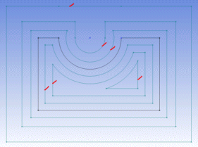
The first image below contains a simple rectangle with a circular cutout on the top. For this illustration, these edges have a fixed constraint and appear as black. It has been offset three times to the outside and three times to the inside. Sketching pencil symbols are shown where the cursor was placed for each offset.
On the first inside offset, closest to the profile, you will see that all the curves have been offset and trimmed appropriately. On the next inside offset, you will notice that the line on the upper left of the original profile has been eliminated as it has collapsed out. Finally, on the third inside offset, you will see a single triangular shape (with an arc for one side) as at this distance, offsetting the bottom line and the top arc intersect, splitting the result into two possible areas. The cursor location determines that this is the result.
Now, looking at the first outside offset, you will see that the arc has been extended to its intersections with the top line offsets. In the second outside offset, the lines would no longer intersect the arc, so the arc is 'extended' with tangent lines from its ends. Finally, on the third outside offset, the radius of the arc has collapsed to zero or less, so it is eliminated.

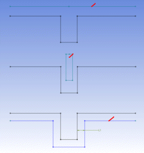
The second image below shows a line with a simple rectangular notch, repeated three times, and again in each case the original curves are fixed so they show up as black. Also again, sketching pencil symbols are shown where the cursor was placed for each offset. In the upper part of the image, it has been offset such that the notch has been collapsed out. In the center part of the image, the cursor was placed in the area being collapsed out. This is to illustrate the importance of where you place the cursor! In the lower area, you can see how a single dimension makes the entire offset profile fully constrained.


