


The following topic(s) are discussed:
There are two basic ways of transferring a BladeGen geometry into BladeEditor
Importing
If you import the geometry, the connection to the BladeGen geometry is maintained, and blade geometry changes must be made by editing the upstream Blade Design cell.
Loading
If you load the geometry, native BladeEditor features are created to represent the complete geometry, the connection to the BladeGen geometry is lost, and all geometry changes must be made by editing the Geometry cell.
Linking from a Blade Design cell to a Geometry cell causes the BladeGen geometry to be imported into BladeEditor. The desired import options should be set in the Blade Design cell properties. (See Table 9.2: BladeGen Blade Design Cell Properties for more information.) After you make the link, the Geometry cell should be updated to process the imported geometry.
Note: If you edit the Geometry cell before updating it, then
the ImportBGD feature details that are shown in BladeEditor may not accurately
reflect the Blade Design cell properties. To refresh the ImportBGD
feature properties, click ![]() in BladeEditor. It is not recommended that you edit the ImportBGD
properties inside BladeEditor because they will be overwritten by the
properties from the Blade Design cell the next time you update the
Geometry cell.
in BladeEditor. It is not recommended that you edit the ImportBGD
properties inside BladeEditor because they will be overwritten by the
properties from the Blade Design cell the next time you update the
Geometry cell.
For details on importing BladeGen geometries, see Transferring Blades from Ansys BladeGen.
For details on loading BladeGen geometries, see Loading and Modifying Blades from Ansys BladeGen.
If you want to clear a BladeEditor session while maintaining the link to the upstream cell, do not use the Start Over command from the File menu in BladeEditor. Doing so would erase the incoming data from any upstream connections — notably when there is an upstream link to a BladeGen system. Instead, return to the Project Schematic pane, right-click the Geometry cell and select Reset from the shortcut menu. When you subsequently edit the Geometry cell, the upstream data is imported correctly.
When a spline is initially created, it is uniquely defined by its fit points.
Spline control points (if exposed via the option when the spline is created or through the spline edit) can be modified using the normal drag operation. It is recommended that you use control points rather than fit points when manipulating splines. If you move any of the fit points, the spline may or may not be uniquely-defined, depending on the way in which you move the points.
Assuming that you have already created the hub when you initially imported the BladeGen model, you can add a hub fillet using the following procedure:
Edit the Geometry cell.
In BladeEditor/DesignModeler, in the feature tree, right-click the first feature that is listed below both the hub and blade features, then select Insert > Fixed Radius from the shortcut menu.
This inserts a new Blend feature immediately above the feature that you right-click in the tree.
Select an edge along the intersection of a blade and the hub, for each edge that is to have a fillet of a specified size.
You may need to use viewer toolbar icons to manipulate the view beforehand. If you cannot select an edge, confirm that the selection filter is set for selecting edges (the
 toolbar icon).
Select Extend to Limits from the toolbar.
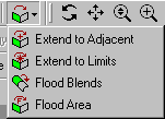
This causes the selected edge to reach as far as possible around the blade.
Click Apply beside the Geometry property in the details view.
Set an appropriate value for the Radius property in the details view.
Click
 .
.
Assuming that you have not created the fluid zone when you initially imported the BladeGen model, you can create a fluid zone for a full, 360° impeller model using the following procedure:
View the Blade Design cell properties.
To do this, right-click the Blade Design cell and select Properties from the shortcut menu.
In the Properties pane, with Geometry Transfer Type set to
Import BGD, ensure that Create All Blades is selected.Update the Geometry cell if required.
Edit the Geometry cell.
Create a Revolve feature using the master profile, and revolve it around the axis for the full 360° to generate the annulus volume.
Use an Enclosure feature to subtract the solid impeller from the annulus to generate the required full 360° fluid zone.