The Aqwa Co-simulation Setup Wizard comprises three steps:
The wizard will go through the process of setting up the connection between the AeroDyn inputs and the Rigid Dynamics project, creating Aqwa data objects in the Rigid Dynamics project, defining the remaining information for the co-simulation analysis, establishing the co-simulation Twin Builder project and finally, running the co-simulation.
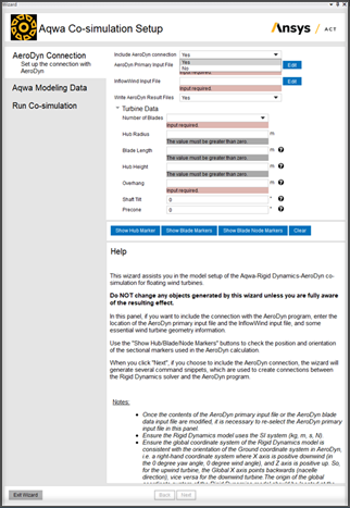
This step aims to generate scripts in the Rigid Dynamics model to set up and activate the connection between the Rigid Dynamics solver and the AeroDyn program. Aerodyn from OpenFAST version 3.0.0 is used for this feature. The Aerodyn input files must be prepared for this specific version, including the AeroDyn primary input file, InflowWind input files, Blade Data input file, and Airfoil Data input files. If you want to skip this process, select No for the Include AeroDyn Connection option and proceed to the next step. If Yes is selected (see Figure 8.42: AeroDyn Connection Setup), additional AeroDyn and turbine information must be provided. The required information includes the following:
AeroDyn Primary Input File: The path of the AeroDyn primary input file.
InflowWind Input File: The path of the InflowWind input file. For more information, refer to the InflowWind Users Guide.
Write AeroDyn Result Files: Choose whether to generate AeroDyn Result files.
Turbine Data: The following parameters follow the same definition described in the Driver Inputs and Options section of the AeroDyn User Guide:
Number of Blades: The amount of blades which the turbine model has, with a selection of 1 to 3.
Hub Radius: The radius of the hub, measured from the center-of-rotation to the blade root along the (possibly preconed) blade-pitch axis.
Blade Length: The length of the blade, which is measured from the blade root to the blade tip.
Hub Height: The height of the hub center measured from the origin of the Global coordinate system of the Rigid Dynamics project, which is the global Z-coordinate value of the hub center.
Overhang: The global X-coordinate value of the hub center. Overhang is positive downwind, so use a negative number for upwind rotors.
Shaft Tilt: The angle between the rotor shaft and the horizontal plane. Positive shaft tilt means the downwind end of the shaft is the highest.
Precone: The angle between a flat rotor disk and the cone swept by the blades, positive downwind (upwind turbines have negative Precone for improved tower clearance).
Note: To ensure the consistency of the AeroDyn connection scripts and the AeroDyn input files, the path of the AeroDyn primary input file needs to be re-selected if any settings in the AeroDyn input files have been modified.
The data transfer between AeroDyn and Rigid Dynamics is conducted through the nodes, which represent the turbine geometry parts in a condensed form. For each node, we use a marker to indicate it. The marker consists of a position and an orientation. Namely, it is equivalent to the local coordinate system of the geometry part represented. For example, the hub marker is located at the hub center, and the shaft tilt will influence its orientation. The hub marker, blade marker and blade node maker are determined using the work described by Jonkman & Jonkman [1].
When expressed in the coordinate system terms, the hub marker orientation is:
X-axis: Pointing along the hub centerline in the nominally downwind direction
Y-axis: Orthogonal with the x- and z-axes such that they form a right-handed coordinate system
Z-axis: Perpendicular to the hub centerline with the same azimuth as Blade 1
Similarly, the blade marker is located at the intersection of the pitch axis and the blade root of each blade. Its orientation is as follows:
X-axis: Orthogonal with y- and z-axes such that they form a right-handed coordinate system
Y-axis: Pointing towards the trailing edge of the blade and parallel to the chord line at the zero-twist blade station
Z-axis: Pointing along the pitch axis towards the tip of the blade
The blade node marker is located at the aerodynamic analysis node listed in the Blade Data Input file. Its orientation is as follows:
X-axis: Orthogonal with y- and z-axes such that they form a right-handed coordinate system
Y-axis: Aligned with the local chord line pointing towards the trailing edge
Z-axis: Directed along the blade towards the tip
Note: The turbine, which can be simulated by this Add-on, is limited to the single basic horizontal axis wind turbine. The initial orientation of Blade 1 should have the same azimuth of the global z-axis and should not have any rotation about the hub rotation axis. The following blades (Blade 2 and Blade 3) spread equally in the rotation plane in an anti-clockwise order, viewing towards the downwind direction. The nacelle and hub should not have any yaw angle.
Three buttons are available to help the inspection of the correctness of the AeroDyn input being set up. They are Show Hub Marker, Show Blade Markers, and Show Blade Node Markers. By clicking on them, the coordinate systems of the corresponding markers will be generated in the outline tree of the Rigid Dynamics project.
The setup scripts for AeroDyn will be written into the Rigid Dynamics project when the Next button is clicked. The scripts will activate the connection between the AeroDyn program and the Rigid Dynamics solver while the Rigid Dynamics project is being solved.
Note: The AeroDyn primary input file specifies the path of the Blade Data Input file and the Airfoil Data Input file while the InflowWind Input file specifies the path of the wind file if necessary. All the AeroDyn and InflowWind files will not be embedded into the Rigid Dynamics FMU package. However, they should be available and accessible in their claimed directories while the Rigid Dynamics project or the co-simulation project is being solved.
Note: The wizard assumes the blade and tower sectional nodes will follow the requirements in the AeroDyn User Guide. The local elevation of the tower nodes must increase from the lowest (tower-base) to the highest (tower-top) elevation. The first and last blade nodes must be located at the most inboard (blade root) and most outboard (blade tip) points, respectively. The tower nodes should not be located at the multiple structures that have relative motions, and neither should the blade nodes of each blade. Otherwise, the AeroDyn connection scripts could be inaccurate.
Note: As AeroDyn uses the SI system (kg, m, s, N), the Rigid Dynamics project must also use the same unit system if the AeroDyn connection is included.
More notes about this step can be found in the Help section of the wizard.
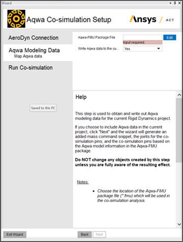
The Aqwa Modeling Data step is used to record the file location of the Aqwa FMU package file, which will be used in the co-simulation analysis.
Based on the Aqwa input files in the Aqwa FMU package, if Yes is selected for , this step can map Aqwa data into the current Rigid Dynamics project when is clicked, similar to the Mapping Aqwa Data option in the Aqwa Co-simulation toolbar. If No is selected, there will be no changes to the current Rigid Dynamics project when proceeding to the next step. No can be selected when a Rigid Dynamics FMU package file that matches the selected Aqwa FMU Package File in this wizard step is already available or can be obtained without writing the Aqwa data into the current project.
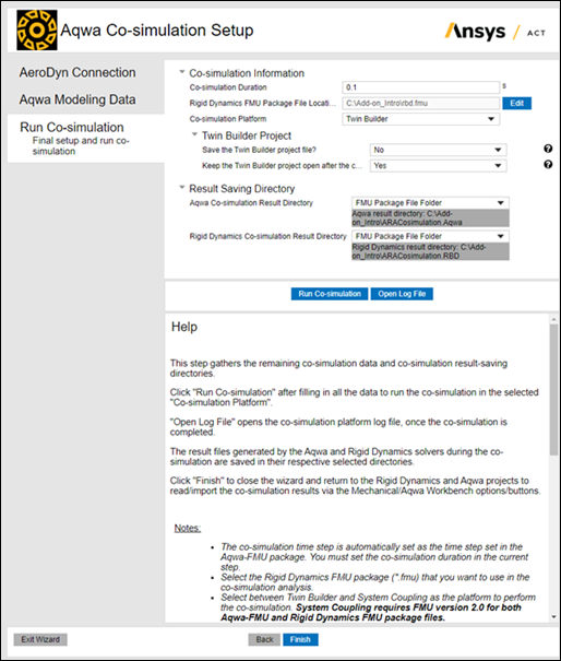
The Run Co-simulation step sets up the remaining information required to run the co-simulation and the result saving directories for co-simulation results. Once all the requested information is provided, selecting the Run Co-simulation button will trigger the establishment of the co-simulation project and the running of the co-simulation analysis. Upon completion, click Finish to close the wizard, which will clear the values recorded or provided in the wizard.
The remaining information required to run the co-simulation includes:
: The co-simulation duration set in the wizard will decide the final duration of the co-simulation analysis conducted by the wizard. During the co-simulation, it will replace the co-simulation duration previously set for the Aqwa FMU package and the Rigid Dynamics FMU package.
: For the co-simulation with Aqwa and AeroDyn, the Rigid Dynamics project should have the Aqwa data mapped and the connection with the AeroDyn inputs established before generating the FMU package. The Rigid Dynamics FMU package can then be generated using the Write Input File option.
: Select between Twin Builder and System Coupling as the co-simulation running platform. If Twin Builder is selected, further Twin Builder project-related options will appear.
: The version of Twin Builder used to run a co-simulation analysis is the same as Ansys Workbench. Selecting either Save the Twin Builder project file or Keep the Twin Builder project open after the co-simulation can decide whether the Twin Builder co-simulation project will be saved or kept open after the co-simulation ends, respectively. If Yes is selected for the Keep the Twin Builder project open after the co-simulation option, the Twin Builder project needs to be closed manually before continuing to work in the wizard. It is recommended to keep the Twin Builder project open the first time you run the co-simulation to ensure that no error messages show in the Twin Builder message panel.
Note: System Coupling requires FMU version 2.0 for both Aqwa and Rigid Dynamics FMU package files. Twin Builder supports both FMU version 1.0 and 2.0.
The co-simulation results files generated by the Aqwa and Rigid Dynamics solvers will be saved respectively in the selected Aqwa Co-simulation Result Directory and Rigid Dynamics Co-simulation Result Directory. These are the available directory options:
Project Solving File Directory: Specifically for the Aqwa results, it refers to the solver files directory of the Aqwa project where the Aqwa FMU package was created. For the Rigid Dynamics results, it refers to the solver files directory of the first Rigid Dynamics system in the project where the wizard is open. The full path of the directory will be shown underneath the option once it is selected.
FMU Package File Directory: It refers to the directory that contains the corresponding (Aqwa/Rigid Dynamics) FMU package file. The full path of the directory will be shown underneath the option once it is selected.
Manual: It enables the manual selection for the result file saving directory.
Note: Irrespective of the selected result saving option, the result files are saved in a folder named ARACosimulation.Aqwa for Aqwa or ARACosimulation.RBD for Rigid Dynamics inside the selected result directory.
The button can work on the condition that the first two wizard steps passed without any error and all the requested information is provided in the current wizard step. In the Twin Builder or System Coupling project created by the wizard, the Aqwa FMU package and the Rigid Dynamics FMU package selected in the wizard will be linked and run as a co-simulation system. The System Coupling project will run via Command Prompt without a User Interface. However, the Open Log File button can work after the co-simulation finishes. It shows the running log file of the selected Co-simulation Platform.
After the co-simulation analysis finishes successfully, the wizard will try to copy back the co-simulation results created by the Aqwa and Rigid Dynamics solvers from the Twin Builder or System Coupling project temporary directory to the Aqwa and Rigid Dynamics project directories. When Twin Builder is used, the detailed copying paths for the different solver result files will be shown in the Twin Builder message panel and the Twin Builder running log file if the file copying process succeeds.
The Rigid Dynamics results can be manually imported back into the Rigid Dynamics project via Read Result Files while the Aqwa results can be accessed via AqwaGS, AqwaReader and Aqwa Workbench where the Import Co-simulation Results option can be selected to import the co-simulation results to the Hydrodynamic Response Solution. Once loaded, the Twin Builder or System Coupling project can also show the co-simulation pin values along with the co-simulation duration.
Note: If you encounter any error messages or a stop in the progress bar while working in the Twin Builder project, it is recommended to find the Aqwa INPUTFILE.MES file and Rigid Dynamics solve.out file under the subfolders of the temp folder in the Twin Builder project directory and check the messages in them.
Note: On the Windows system, the 'Opens with' application must be set with a text editor for the .out and .log files first to enable the Open Log File button to function properly. To set the 'Opens with' application on a Windows system, right-click an *.out file, select Properties in the list, and in the General tab of the Properties window, click the 'Change...' button in the 'Opens with' property, then select Notepad or any other text editor application.