


This window lets you Define the zoning for your 3D Part.
Box
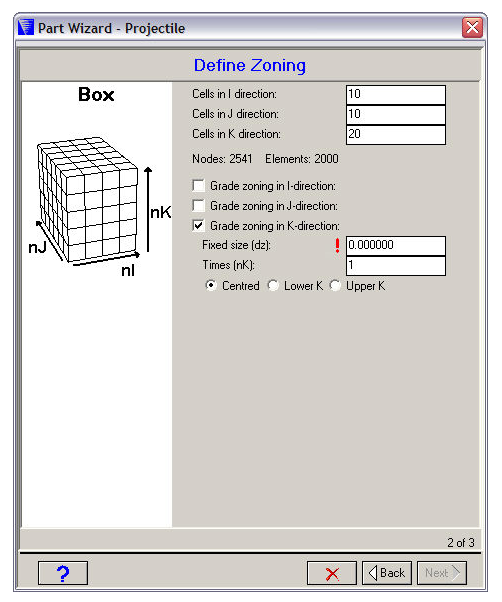
- Cells
The number of cells (elements) you want to use in the I, J and K directions. The corresponding number of nodes and elements required for your part will be displayed below.
- Grade zoning
Check the boxes if you want to grade your zoning in any direction.
If you choose this option you can specify a range of cells which have a fixed size. The remaining cells will be smoothly graded to fit the overall dimension of the box you specified in the previous window.
Fixed size
The dimension you want to use for the fixed size cells.
Times
The number of fixed size cells you want to use.
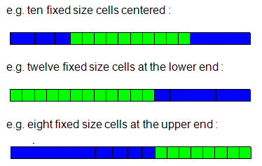
Position
Specify where you want to place the fixed size cells relative to the full I/J/K range.
- Centered
At the center of the full I/J/K range.
- Lower
At the lower end of the I/J/K range.
- Upper
At the upper end of the I/J/K range.
Cylinder
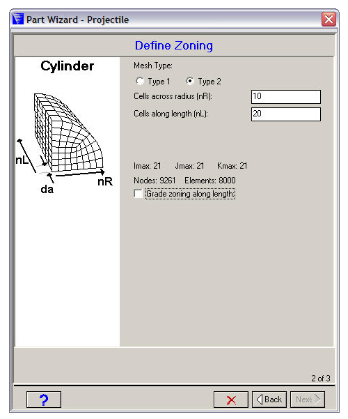
- Mesh Type
Select a Type 1 or Type 2 mesh for your cylinder.
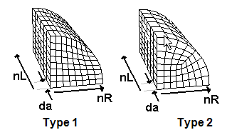
The type 1 mesh is more efficient in using elements, but some elements are not very rectangular (which can reduce the accuracy of your solution).
All the elements of a type 2 mesh are reasonably rectangular, but about a quarter of the elements generated for this mesh are unused.
- Cells across radius
The number of cells (elements) you want to use across the radius of your cylinder.
- Cells along length
The number of cells (elements) you want to use along the length of your cylinder.
- Number of elements
Displayed below the above input fields are the index space that will be used for your Part and the number of nodes and elements required.
- Grade zoning along length
Check this box if you want to grade the zoning along the length of your cylinder (you will be asked to specify a starting increment to use).
Ogive
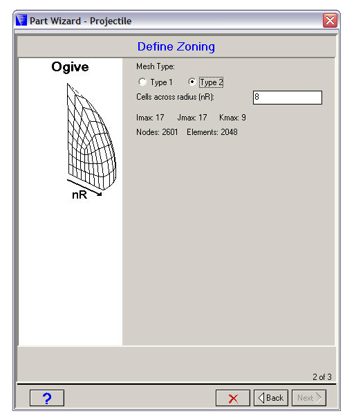
- Mesh Type
Select a Type 1 or Type 2 mesh for your ogive.
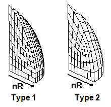
The type 1 mesh is more efficient in using elements, but some elements are not very rectangular (which can reduce the accuracy of your solution).
All the elements of a type 2 mesh are reasonably rectangular, but some of the elements generated for this mesh are unused.
- Cells across radius
The number of cells (elements) you want to use across the radius of your ogive.
- Number of elements
Displayed below the input fields is the index space that will be used for your Part and the number of nodes and elements required.
Sphere
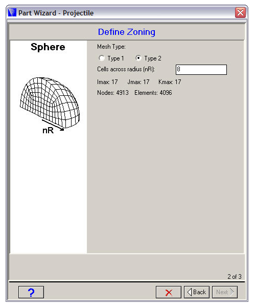
- Mesh Type
Select a Type 1 or Type 2 mesh for your sphere.
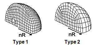
The type 1 mesh is more efficient in using elements, but some elements are not very rectangular (which can reduce the accuracy of your solution).
All the elements of a type 2 mesh are reasonably rectangular, but some of the elements generated for this mesh are unused.
- Cells across radius
The number of cells (elements) you want to use across the radius of your sphere. For solid spheres, there is a maximum limit of 40 cells across the radius. For finer meshes than this, it is recommended that you use the Meshing application, where a hex mesh can be obtained by using the multi-zone and inflation layer operations. For more information see Autodyn Walkthrough Using Meshing in this guide.
- Number of elements
Displayed below the input fields is the index space that will be used for your Part and the number of nodes and elements required.
Hex
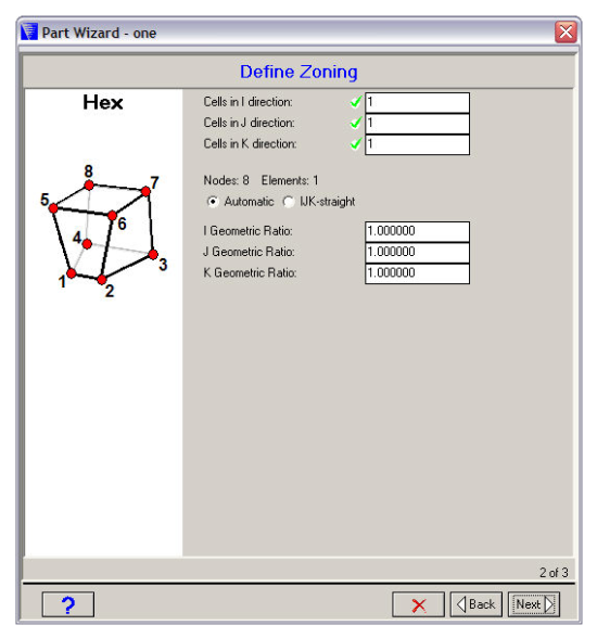
- Cells in I/J/K direction
The number of cells (elements) you want to use in the I, J, and K directions. The corresponding number of nodes and elements required for your part will be displayed below.
- Automatic
Spaces the internal nodes equipotentially.
- IJK-Straight
Spaces the nodes in a straight line equally along each I, J, and K line.
- Geometric Ratios
Input geometric ratios in the fields provided if you want to grade the zoning instead of generating equally spaced nodes.
Frag/Brick
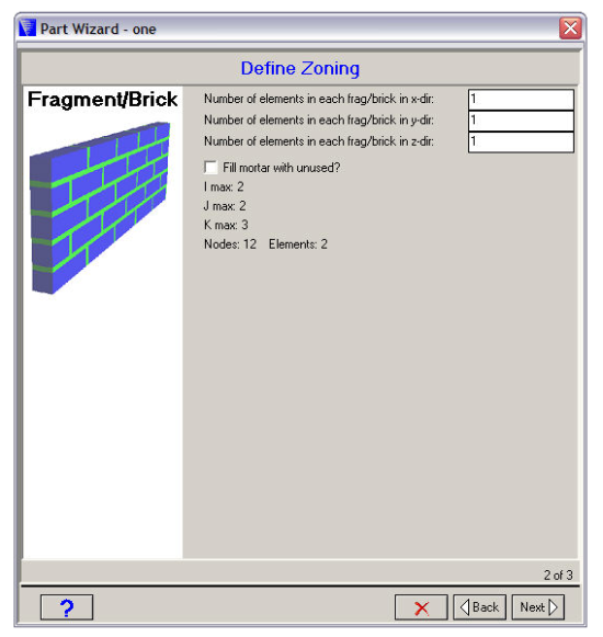
- Number of elements in each fragment/brick
Use these fields to set the number of elements per fragment/brick in the X, Y, and Z directions.
- Fill mortar with unused?
Check this box if you do not want the mortar to be represented as a material.
If you check this box, no elements will be generated for the mortar.
If you do not check this box, elements will be generated for the mortar. (If the mortar thickness is small compared to the dimension of the brick elements, the time step is likely to be reduced significantly.)