


In Autodyn, you build your model in Parts. There are two concepts for node, element and part data storage and processing available.
Structured Parts
For structured parts in Autodyn, all information relating to the mesh and the elements in the mesh is stored and processed using the concept of I, J and K lines (IJK-space). This means that for an element whose quantities are stored at position (I, J, K), the nodes belonging to that element are automatically defined in IJK space as (I-1, J,K), (I, J-1,K), (I-1, J-1,K),.....(see the figure below).
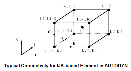
The element connectivity is therefore implicitly defined by the structure within the I, J, K indexing. Information relating to each point in IJK space is also stored in this structure. Furthermore, in this structured approach, the node and element storage and processing is directly linked to the Parts in the model.
Each structured Part is a grid (or group of SPH nodes) that a particular solver operates on.
Autodyn offers many tools for the generation of structured Parts as will be described below.
Unstructured Parts
For unstructured parts an alternative "Unstructured" approach to storing and processing information relating to the mesh is used for the solvers: The basic entities needed in the simulation are the Nodes, Elements, Faces, Joints and so on. In this scheme, these are stored in unique and independent global "Entity" lists, where an entity is a node, element, face, join and so on. Connectivity between entities is determined by cross-referencing to the appropriate global entity list. The data associated with each entity is also stored in a manner most efficient for solving the equations and does not need to follow a set structure/order.
A global list of all elements relating to unstructured Parts is maintained. Each element is given a unique identifying number from one to total number of elements. Each element also has a user element number associated with it for the purposes of model manipulation and user identification.
Each element will have a list of variables associated with it the number and type of variables depending on the type of element (for example a hexahedral element containing an orthotropic material or a triangular shell with a rigid material).
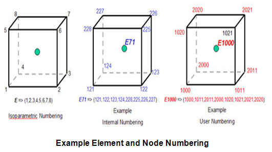
Each element has three numbering systems for its connecting nodes (see figure):
A local isoparametric number; used to loop over the nodes of an element in the correct order and solved the physical equations. Each element with the same topology has the same numbering system.
An internal node number; the physical properties of each node are referenced via the global node lists. A connectivity table is used to cross-reference the local node number to an entry in the physical node list.
A user node number; a number assigned by you to define the element.
For the unstructured solvers in Autodyn, Parts are simply used to allow easy grouping and manipulation of various regions of the model. They are not related to the actual data storage for the elements and nodes, as in IJK-based Parts.
The default definition of a Part currently used for the unstructured solvers is: "A Part is a list of elements of the same classification (volume, shell, beam) that are connected together via the connectivity table of the elements".
Note that within each Part, all elements must be of the same class (volume, shell or beam), but not necessarily the topology. For example a shell Part may contain a mixture of quadrilateral and triangular elements. Nodes are only related to Parts through the element connectivity. Nodes can therefore exist in multiple Parts, for example if the same node is connected to a beam and shell element.
Autodyn doesn't offer any capability of generating unstructured elements and Parts manual. Unstructured elements and Parts can be generated in Ansys Workbench and transferred to Autodyn.
Furthermore unstructured models in MSC.Nastran or LS-Dyna format can also be imported directly into Autodyn.
The following 3D Lagrangian unstructured element types are supported:
Volume elements
8 noded hexahedral elements
6 noded pentahedral elements (to be used as transition elements)
4 noded tetrahedral elements
Shell elements
4 noded quad elements
3 noded triangular elements (to be used as transition elements)
Beam elements
2 noded beam elements
The following 2D Lagrangian unstructured element types are supported:
Volume elements
4 noded quadrilateral volume elements
3 noded triangular volume elements
Note:
The 2D Lagrangian unstructured element types have Beta status and therefore may not be as stable or robust as expected in a general release version.
A 2D or 3D analysis involving unstructured parts with only rigid materials may result in unphysical results, because rigid bodies do not have a minimum time step associated with them and therefore too large displacements may occur from cycle to cycle and contact can be missed. For this type of analysis, you need to manually define a small time step for the analysis.
This panel lets you create structured Parts and modify the structured and unstructured Parts of your model.
- Part List
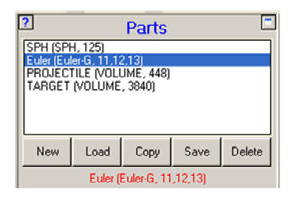
The box at the top of this panel lists the Parts you have currently defined for your model. You can select a Part in this list.
The size of the structured parts is displayed in terms of maximum I, J and K of the part (see Part Euler above). Structured SPH parts are displayed in terms of the total number of SPH nodes, because SPH parts don't use elements.
For unstructured parts the size of part is displayed as the total number of elements (see Parts PROJECTILE and TARGET above).
- New
Create a new structured part.
- Load
Load a structured Part from a Part Library.
This option is not available for unstructured Parts because for these types of Parts the Ansys Workbench project data storage can be used as a part library.
Only part libraries created in the current version of Autodyn can be imported.
- Copy
Copy an existing Part to a new Part. This is valid for both structured as well as unstructured Parts.
- Save
Save structured Parts to a Part Library. This option is not available for unstructured Parts because for these types of Parts the Ansys Workbench project data storage can be used as a part library.
- Delete
Delete a structured/unstructured Part.
The remaining dialog in this panel depends on the Solver used by the selected Part.
All Structured Solvers except SPH
SPH Solver
Unstructured Solvers

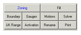
- Zoning
Zone a structured Part.
Unstructured Parts cannot be generated; an unstructured Part can only be translated, rotated or scaled.
- Fill
Fill a part with materials and initial conditions.
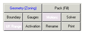
- Geometry (Zoning)
Define geometric objects for SPH Parts
- Pack (Fill)
Pack geometric objects with SPH nodes.
- Boundary
Apply boundary conditions to a Part.
- Gauges
Assign gauges to a part.
- Motions
Assign motion constraints to a structured ALE Part.
- Solver
Select solver options for a Part.
- IJK Range
Modify the IJK range for a structured Part
- Activation
Set activation / deactivation times for a structured Part.
For unstructured Parts activation / deactivation time cannot be set (they are always activated).
- Rename
Rename a Part.
Set print ranges for a Part.
This option is not available for unstructured Parts.