


This window lets you Define the zoning for your 2D Part.
Box
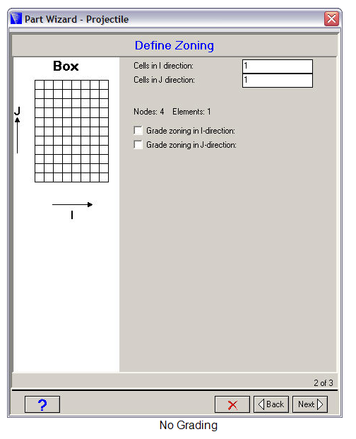
- Cells
The number of cells (elements) you want to use in the I and J directions. The corresponding number of nodes and elements required for your part will be displayed below.
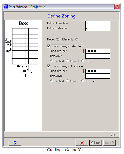
- Grade zoning
Check the boxes if you want to grade your zoning in any direction.
If you choose this option you can specify a range of cells that have a fixed size. The remaining cells will be smoothly graded to fit the overall dimension of the box you specified in the previous window.
Fixed size
The dimension you want to use for the fixed size cells.
Times
The number of fixed size cells you want to use.
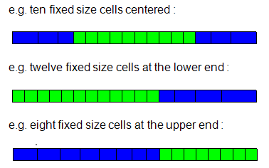
Position
Specify where you want to place the fixed size cells relative to the full I/J range.
Centered - at the center of the full I/J range
Lower - at the lower end of the I/J range
Upper - at the upper end of the I/J range
Circle
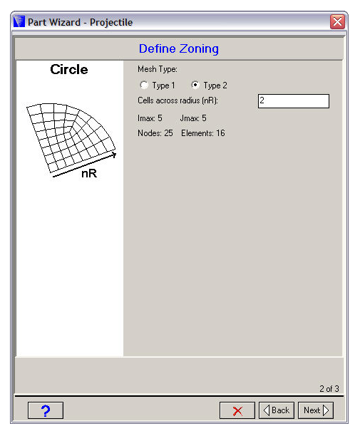
- Mesh Type
Select a Type 1 or Type 2 mesh for your circle.
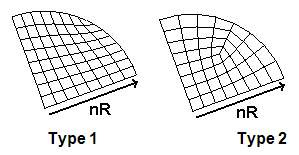
The type 1 mesh is more efficient in using elements, but some elements are not very rectangular (which can reduce the accuracy of your solution).
All the elements of a type 2 mesh are reasonably rectangular, but about a quarter of the elements generated for this mesh are unused.
- Cells across radius
The number of cells (elements) you want to use across the radius of your circle.
- Number of elements
Displayed below the input fields is the index space that will be used for your Part and the number of nodes and elements required.
Ogive
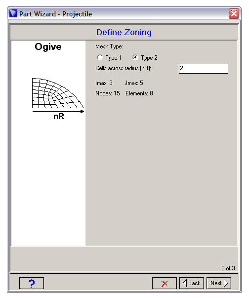
- Mesh Type
Select a Type 1 or Type 2 mesh for your ogive.
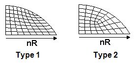
The type 1 mesh is more efficient in using elements, but some elements are not very rectangular (which can reduce the accuracy of your solution).
All the elements of a type 2 mesh are reasonably rectangular, but some of the elements generated for this mesh are unused.
- Cells across radius
The number of cells (elements) you want to use across the radius of your ogive.
- Number of elements
Displayed below the input fields is the index space that will be used for your Part and the number of nodes and elements required.
Wedge
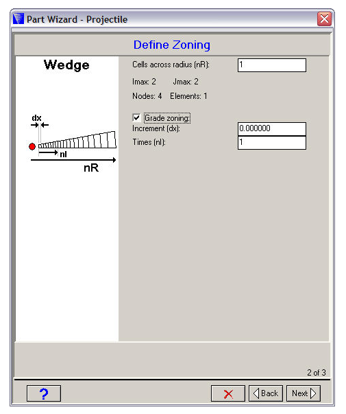
- Cells across radius
The number of cells (elements) you want to use across the radius of your wedge.
- Number of elements
Displayed below the first input field is the index space that will be used for your Part and the number of nodes and elements required.
- Grade zoning
Check this box if you want to grade your zoning.
If you choose this option you can specify a range of cells which have a fixed size. The remaining cells will be smoothly graded to fit the overall dimension of the box you specified in the previous window.
Increment
The dimension you want to use for the fixed size cells.
Times
The number of fixed size cells you want to use.
Rhombus
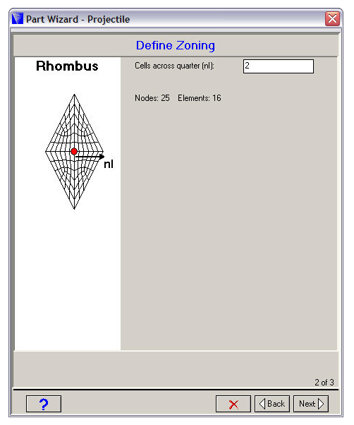
- Cells across quarter
The number of cells (elements) you want to generate across a quarter of the rhombus.
- Number of elements
Displayed below the input field is the index space that will be used for your Part and the number of nodes and elements required.
Quad
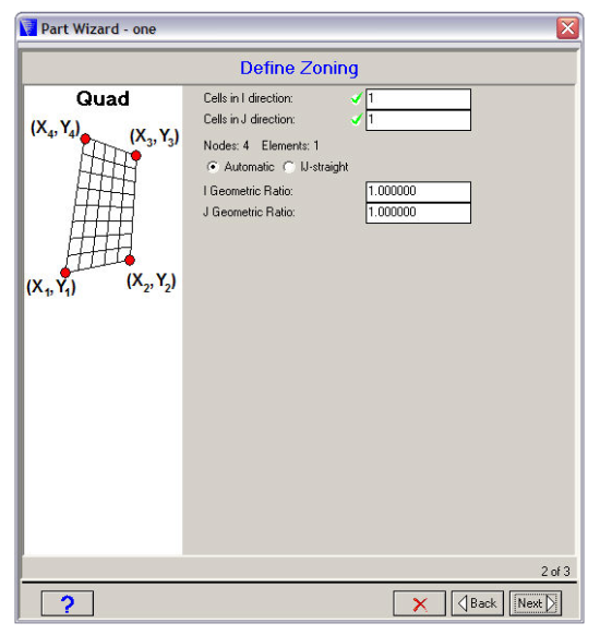
- Cells in I/J direction
The number of cells (elements) you want to use in the I and J directions. The corresponding number of nodes and elements required for your part will be displayed below.
- Automatic
Select this option if you want the internal nodes to be spaced equipotentially.
- IJ-Straight
Select this option if you want the nodes along each I and J line to be equally spaced along a straight line.
- Geometric Ratios
Input geometric ratios in the fields provided if you want to grade the zoning instead of generating equally spaced nodes.