An overview of how to access Autodyn in Workbench is provided below. Full guidance on how to use Workbench is provided in the Workbench User's Guide.
The Workbench user interface consists primarily of a Toolbox region, Project Schematic, toolbar, and menu bar. Depending on the analysis type and/or application or workspace, you may also see other windows, tables, charts, and so on.
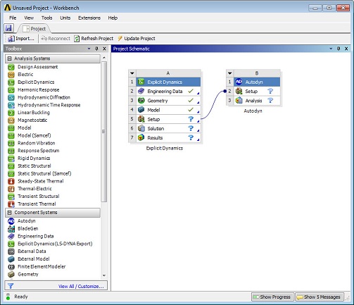
One method of creating a project in Workbench is to drag an item such as a component or analysis system from the Toolbox to the Project Schematic, or double-click on an item in the toolbox to initiate the default action. You can also use the context menus, accessible from a right-mouse click, for additional options. You will view your analysis systems—the components that make up your analysis—in the Project Schematic, including all connections and links between the systems. The individual applications in which you work will display separately from the Workbench user interface, but the results of the actions you take in the applications may be reflected in the Project Schematic.
Full details of how to use Workbench are provided in the Workbench User's Guide.
An Autodyn product license should enable three primary systems in the Toolbox of the Workbench user interface.
Autodyn System
The Autodyn system is located in the Component Systems toolbox of the Workbench user interface. This system enables you to start the traditional Autodyn application and includes pre-processing, solve, and postprocessing options for all Autodyn solvers.
To start the Autodyn application, simply insert an Autodyn system into the project schematic and then double-click the Setup cell.
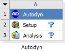
The Autodyn application will start and you can set up, solve, and post-process models in the familiar Autodyn user interface. The default start up mode will be the generation of a new model. The start-up mode can be changed by a right-mouse click the Setup cell, after which you can select:
|  |
After selection of the desired Setup cell setting, double-clicking the Setup cell again will start Autodyn in the required mode.
Note:
Model Name: The database for an Autodyn model will now always be admodel_0.ad. The project name is the now unique identifier for all databases (see below).
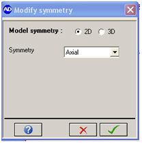
2D/3D symmetry: By default, the Autodyn application assumes you are performing a 3D simulation in the default unit set (mm, mg, ms). To define 2D axial or planar symmetry, use the Setup > Symmetry option in the toolbar after starting the Autodyn application.
 |  |
Note:
Saving a project: To save a model, the recommended approach is to save the Workbench project either from within the Autodyn application (File, Save Project) or from the project page of Workbench. This ensures all data used in the Autodyn Simulation is saved to disk.
Exporting an Autodyn database: The Autodyn database (restart file) can be exported to a file (independent of the Workbench project) using the File, Export options in the Autodyn application.
Refer to Autodyn in the Workbench User's Guide for further details on the operations and properties available for an Autodyn system.
Explicit Dynamics system
The system contains a number of unique features for explicit dynamic simulation inside Workbench:
Unidirectional and bidirectional links to CAD geometry
Links to DesignModeler
Advanced meshing capabilities tailored for Explicit Dynamics analysis
Mesh independent loading and boundary conditions
Fully parameterized engineering data, geometry, initial conditions, loads, boundary conditions
Automated "What If" analysis capability
Links to design exploration tools.
Expressions are supported for Explicit, Explicit parallel, and Autodyn, but not Autodyn parallel analyses
The full capabilities of the Explicit Dynamics system are described in Explicit Dynamics Analysis Guide in the Explicit Dynamics Analysis Guide.
Models set up in the Explicit Dynamics system can be persistently linked to an Autodyn system to transfer material data, mesh, connections, loads and constraints, analysis settings, and so on into Autodyn.
For modeling complex geometries in Ansys Autodyn, we recommend you define the FE components of the model in an Explicit Dynamics system then transfer the model setup to the Autodyn system and add on your Euler-SPH regions and explicit FSI/Coupling as required.
Mesh System
The Mesh system is located in the Component Systems toolbox of the Workbench user interface. This system can be linked to either an Autodyn or Explicit Dynamics system and enables you to link to your model geometry and generate a mesh. The mesh can then be transferred to an Autodyn or Explicit Dynamics system for subsequent analysis.
This system enables you to use a workflow to link Autodyn models to CAD/geometry and meshing tools. However the link is not persistent, which means that with every update of the workflow system, the definitions made in Autodyn (material filling, boundary condition assignment, etc.) are lost and have to be re-applied.
Therefore we recommend using the Explicit Dynamics system to link to CAD/geometry and generate a mesh for use in Autodyn where loads, constraints and material assignments are maintained after any change to the geometry or mesh.
Linking different systems
If the mesh/geometry of the application to be solved in Autodyn cannot be made with the simple model building tools available in the Autodyn application, we recommend the following approaches to build the Autodyn model.
Explicit Dynamics => Autodyn
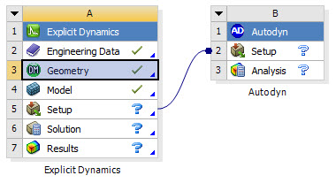
The recommended approach for bringing Lagrangian FE based models with complex geometries into Autodyn is to start off with an Explicit Dynamics system.
Define material data using the Engineering Data application
Link directly to CAD Geometry or use DesignModeler to generate geometry directly or adapt CAD geometry for simulation purposes
Mesh the geometry and define connections (Contact, Joins, Spotwelds)
Assign initial velocities to components
Apply loads and constraints directly to the geometry
Define solution controls and outputs
Solve and Post process results
To transfer the model from an Explicit Dynamics system to the Autodyn application, link the Setup cell of the Explicit Dynamics system to the Setup cell of the Autodyn system. Open the Autodyn application by double-clicking the Autodyn system Setup cell. All relevant model information defined in Engineering Data, Geometry, Model and Setup components of an Explicit Dynamics system are transferred into the Autodyn application.
Once in the Autodyn application, you can complete the model setup (for example, add Euler and SPH regions) then solve in the Autodyn application.
The link generated between the Autodyn and Explicit Dynamics system is persistent. You can make changes to the model defined in the Explicit Dynamics system, update the Explicit Dynamics system Setup cell, then update the Autodyn system Setup cell. The latest model definition will be transferred into the Autodyn model while retaining additional features present only in the Autodyn application. This makes it very easy to make changes to model.
Note:
Changes made to the model in the Autodyn application are not transferred back to the Explicit Dynamics system. The link is one-way.
To avoid overwriting changes you make in the Autodyn application, we recommend that if a portion of the model is defined in the Explicit Dynamics system (for example and initial velocity) then only make changes to this in the Explicit Dynamics system. Transfer to the Autodyn model using the update procedure described above.
The following functionality is transferred to and used in the Autodyn simulation; however it cannot be edited or reviewed in the Autodyn application:
Local coordinate systems.
Loading defined in tabular form.
General velocity boundary conditions.
Acceleration boundary conditions.
Joint definitions and their conditions.
Pointmass definitions.
Multiple load steps and the corresponding activation/deactivation of loads.
Static Damping coefficient.
Note: The step aware Static Damping coefficient can still be overruled by a global value under Solution Controls by changing the large value to a smaller value.
An increase of the time limit in the Autodyn application will respect the load activation/deactivation of the last load step.
Accelerations and Standard Earth Gravity are passed from the Explicit Dynamics system to the Autodyn application by means of acceleration boundary conditions. In the Autodyn application gravity may be added under Solution Controls, which will be added to the acceleration boundary conditions from the Explicit Dynamics system.
Displacement boundary conditions defined in the Explicit Dynamics system are converted to equivalent velocity boundary conditions in the Autodyn application.
Spot weld breaking criteria defined in the Explicit Dynamics system will be converted from a stress to a force criterion
This link will also transfer parallel processing settings; however the linked Autodyn component system will not directly solve in parallel because the Autodyn system has not started the proper number of worker executables yet. In order for the Autodyn solver to run in parallel, the model (zero) file can be used as input for a parallel solve via the appropriate command line instructions which are described in Establishing a Parallel Processing Environment in the Autodyn Parallel Processing Guide. Alternatively, the parallel settings can be deselected in the component system in order to return to a serial simulation.
Detonation Points transferred from Explicit Dynamics will be updated to reflect changes in the Explicit Dynamics system. Any Detonation Points defined in Autodyn will be lost after updating a linked system.
Meshing => Autodyn
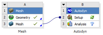
If you only want to transfer a Mesh (of complex geometry) into Autodyn, then this can be achieved using a Mesh system. Start by inserting a Mesh system from the Components toolbox.
Link directly to CAD Geometry or use DesignModeler to generate geometry directly or adapt CAD geometry for simulation purposes
Mesh the geometry
Create Named Selections
Note: When you open the Meshing application, you must set the Physics Preference for the mesh to Explicit. In the Meshing application, you can set the Physics Preference in the wizard that initially comes up when you open the Meshing application, or by clicking on the Mesh object in the tree and changing the Physics Preference field in the Details panel.
To transfer a mesh from the Mesh to the Autodyn application, link the Mesh cell of the Mesh system to the Setup cell of the Autodyn system. Open the Autodyn application by double-clicking the Autodyn system Setup cell. The mesh and Named selections will be transferred to Autodyn.
The link generated between the Autodyn and Mesh systems is not persistent. This means that with every update of the workflow system the definitions made in Autodyn (material filling, boundary condition assignment, and so on) are lost and have to be re-applied.
Therefore, we recommend using the Explicit Dynamics system to link to CAD/geometry and generate a mesh for use in Autodyn, where loads, constraints and material assignments are maintained after any change to the geometry or mesh.
Note:
Connections defined in the Mesh system will not be transferred to the Autodyn application.
Material assignments, Boundary Conditions and Loads defined in the Autodyn application will be lost during the update and will have to be re-applied.
Data Transferred by linking different systems to Autodyn
- Node Coordinates
The nodal coordinates are transferred.
- Mesh Elements
The mesh elements are transferred, noting that Pyramid elements are not supported within Autodyn, so these are converted into two tetrahedra.
- Body Definitions
The definitions of bodies in the Workbench are imported as Parts in Autodyn.
In addition, for Meshing, Simulation and Finite Element Model Objects, the following are transferred.
- Parts Definitions
The definitions of parts (both multi body parts and single body parts) are shown as Components in Autodyn.
- Named Selection
The named selections are represented as Groups in Autodyn. Vertex and Edge Named Selections are transferred as nodal Groups. Surface Named Selections are transferred as a nodal Group and a face Group. Body Named Selections are transferred as a nodal Group and an elemental Group.
- Unit Setup
The units of length are transferred into Autodyn and the units for mass and time are set up as shown in the following table.
Length Mass Time um
pg
ms
mm
mg
ms
cm
gm
us
m
kg
s
in
lbm
ms
ft
lbm
ms
- Material Associations
Each Body (Autodyn Part) transferred is assigned a separate material.
- Shell thickness
Shell parts will be assigned with the thickness as defined in the Workbench object. An initial condition will be created for each part.
- Beam Cross-Sections and Orientations
The beam cross sections associated to elements and their orientations are transferred and applied correspondingly.
In order to update the model in Autodyn to that in the currently selected project page item, make sure that the currently selected cycle is 0 then use the Update Model from Workbench option, found in the Import menu or on the toolbar. This function will update the parts that are in Autodyn to reflect the mesh in Workbench. If a part contains a single material, then the updated parts will be refilled with any materials and initial conditions that are associated. New parts are added to the model as appropriate; deleted parts should be manually removed from the Autodyn model.


