CartSweep Method
The CartSweep approach works best for geometries that are axis aligned. The approach is to generate a Cartesian mesh, convert that Cartesian mesh to sweepable topologies and smooth it out. Next you can use the block editing tools to improve the mesh.
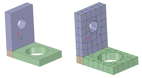
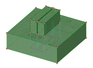
For hex meshing complex models that have features oriented along the global coordinate system, as in the example below, the highlighted faces are found as source faces for swept blocks.
In such cases, you may split the geometry in two and mesh the two parts separately, and then merge the blocks together afterwards. Here the model can be split into three bodies. The two bodies are meshed separately using the CartSweep option and the middle body is meshed using the Standard option. Then the blockings are merged to get the mesh.
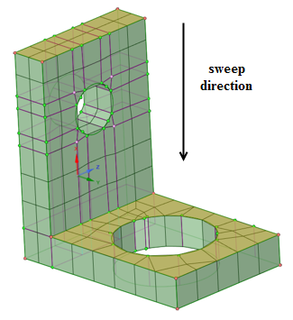
For non-aligned geometries, you can define the sweep direction by selecting a face normal to the sweep direction. Use the Select Source/Target Faces tool guide to set the sweep direction.
You can also create a Named selection for a set of source and target surfaces and select it from the Groups panel instead of selecting the individual surfaces.
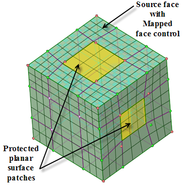
Note: Non-aligned geometries may require additional sizing adjustments as compared to those aligned to the global coordinate system.You can set up a mapped mesh control on the source face to create all mapped blocks with the CartSweep method.
Performance (time of mesh generation) is dependent on two main steps:
Time to generate the Cartesian mesh is dependent on the element size, Cartesian size and tolerance.
Time to convert from Cartesian to sweepable topology is dependent on the number of topological blocks/bodies created. Many stairsteps can slow things down so setting reasonable sizes and defeaturing non-axis-aligned features helps improve performance.
When setting up the model, ensure that the sizes specified are appropriate for capturing the features.
Unlike other mesh methods, reducing the Element size may cause the mesh to fail. Setting appropriate sizes is key to obtaining a good mesh.
Use Element size to define the final mesh sizes.
Use Cartesian size to define the size above which features are captured in the mesh. Defeaturing is done based on Cartesian size:
Set an explicit Cartesian size to define the size that the Cartesian mesher will use to capture features. Use a smaller Cartesian mesh size to capture features without increasing final mesh size.
In the example, the Element size is 4 mm, while a Cartesian size of 1 mm is used to capture the gap.
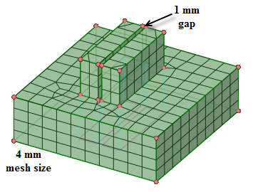
Alternatively, a smaller Element size can be used to capture the gap.
Set
0to disable defeaturing. This uses a slightly different approach to calculating the Cartesian mesh size (using key point blocking).Set
-1for Automatic where the Cartesian size is the same as Element size.
There are two options to control the Grid Spacing in the Cartesian mesh.
Uniform size - This option will split the model uniformly based on the specified Cartesian size.
Key-point splits - This option will split the model at the feature points with the specified tolerance in between the feature lines.
The Key Point tolerance is applied to the Cartesian size. Use a Key Point tolerance of
0.5or0.1. If the mesh is not as desired, vary the Cartesian size instead.
Removing fillets/chamfers can help improve success of meshing.
For models with fillets/chamfers, you can simplify the geometry by removing the fillets/chamfers, or drafts, and then generate the mesh. Then, you can use the Load option to load the blocking for the simplified model over the full-featured model. Generate the mesh and use the editing tools to clean up the mesh to re-use with the original geometry.
For simple models, you can apply sizing and boundary layer controls before generating the mesh. For complex models, you should use sizing and boundary layer controls after generating the initial blocking and mesh.
For selective meshing workflows, first mesh the bodies using the CartSweep method and then proceed to mesh the other bodies. The CartSweep method does not support pre-meshed adjacent bodies.
The Cartsweep method may not work well with shared topology.
Planar surface patches can be preserved with the CartSweep method by creating Named Selections for protecting topology. The Named Selections should include ''protected'' (case-insensitive) at the beginning or as a prefix to the name (for example, PROTECTED-SIDE, ProtectedFaces, protected-outlet).
The example shows a mapped mesh control defined on the source face to create all mapped blocks. The planar surface patches have been preserved by creating Named Selections.