


Creating a Size Control on an Edge
- On the ribbon, click Size
 .
. - Click the Select Edges
 tool
guide and select an edge to which you want to add a local size control. You may
use Box Select to choose multiple edges simultaneously. Note: You may apply a size control to blocking edges or geometry edges. If the Ghost blocked geometry option is enabled (default) and the mesh has been generated, blocking edges will be selected. To select geometry edges instead, disable the Ghost blocked geometry option or hide the blocking in the Structure tree.
tool
guide and select an edge to which you want to add a local size control. You may
use Box Select to choose multiple edges simultaneously. Note: You may apply a size control to blocking edges or geometry edges. If the Ghost blocked geometry option is enabled (default) and the mesh has been generated, blocking edges will be selected. To select geometry edges instead, disable the Ghost blocked geometry option or hide the blocking in the Structure tree. - In Size Options, choose Use element
size
or
Use edge division
 for the
sizing control.
for the
sizing control. - (Optional) Choose an Edge Biasing
 option.
Option Description No Bias 
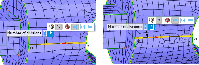
No biasing is applied to the edge. Elements are uniformly sized. Linear Bias: Right

or
Linear Bias: Left

This is a single side bias based on the Bias method selected.
- When By factor is selected, the bias factor is divided linearly across all elements.
- When Height and ratio is selected, the edge biasing can be set by the height and ratio specified. Specify the height and ratio at the Start (V1) or End (V2) vertex (depending on the biasing direction) of the blocking edge selected. Height 1 and Height 2 are the heights applied at the Start (V1) and End (V2) vertices indicated in the display.
An arrow is shown on the edge to indicate the direction of increase in size.
 Note: Select block edges when the Height and ratio option is used.
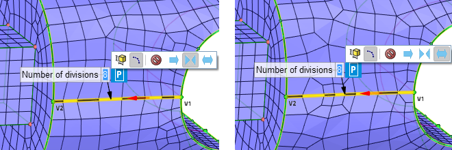
Bell Curve Bias

or
Exponential Bias

This is a both sides bias based on the Bias method selected.
- When By factor is selected, the bias factor is divided geometrically between all elements.
- When Height and ratio is selected, the
edge biasing can be set by the height and ratio specified.
Specify the height and ratio at the Start (V1) and End (V2)
vertex of the blocking edge selected.
- The Height values are defined at the ends of the edge. Height 1 (H1) and Height 2 (H2) are the heights applied at the Start (V1) and End (V2) vertices indicated in the display.
- For Exponential biasing, the ratio values should be greater than 1.
- For Bell Curve biasing, the ratio values should be less than 1.
An arrow is shown on the edge to indicate the direction of increase in size.
 Note:
Note:- Select block edges when the Height and ratio option is used.
- Specify different values for height 1 and height 2 (or ratio 1 and ratio 2) to ensure that the Height and ratio method is used for edge sizing. If the values are identical, the mesher will revert to sizing based on bias factor.
- Repeat steps 4-7 until you are satisfied with the previewed size. Then press
Enter a second time or click
Complete
 to apply
the new size.
to apply
the new size.