Setting the Mesh Type on a Face
- On the ribbon, click Map/Sweep
 .
. - Click Select face
 .
Note: The Map/Sweep control can be applied to geometry faces or block faces. If the Ghost blocked geometry option is enabled (default) and the mesh has been generated, blocking faces will be selected. To select geometry faces instead, disable the Ghost blocked geometry option or hide the blocking in the Structure tree.
.
Note: The Map/Sweep control can be applied to geometry faces or block faces. If the Ghost blocked geometry option is enabled (default) and the mesh has been generated, blocking faces will be selected. To select geometry faces instead, disable the Ghost blocked geometry option or hide the blocking in the Structure tree. - In the Mapping Options panel, choose a mesh
type.
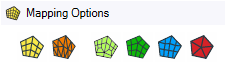 Options are:
- Mapped Quadrilateral
 :
(Default) Instructs the mesher to create a structured face mesh with all
quads.
:
(Default) Instructs the mesher to create a structured face mesh with all
quads. - Mapped Triangles
 :
Instructs the mesher to create a structured face mesh with all triangles.
:
Instructs the mesher to create a structured face mesh with all triangles. - Semi-structured
 : Instructs the mesher to create a semi-structured face mesh with all quads.
For more details, see Semi Structured Mesh Type.
: Instructs the mesher to create a semi-structured face mesh with all quads.
For more details, see Semi Structured Mesh Type. - Free Quadrilateral
 :
Instructs the mesher to create a free face mesh with all quads.
:
Instructs the mesher to create a free face mesh with all quads. - Free Quadrilateral Dominant
 : Instructs the mesher to create a free face mesh
with mostly quadrilaterals. You can also choose to use the Prime surface
mesher with this option.
: Instructs the mesher to create a free face mesh
with mostly quadrilaterals. You can also choose to use the Prime surface
mesher with this option. - Free Triangles
 :
Instructs the mesher to create a free face mesh with all triangles. You can
also choose to use the Prime surface mesher with this option.
:
Instructs the mesher to create a free face mesh with all triangles. You can
also choose to use the Prime surface mesher with this option.
- Mapped Quadrilateral
-
If the face is only attached to four edges and four vertices the
mapping is clear. If the face has more than four edges/vertices attached, you need to
define how the software should map/submap the face by marking the vertices
appropriately.
To set the vertex type:
Select vertices
 is
activated and the toolbar appears.
is
activated and the toolbar appears.
Select the vertex type (default is end vertex) and then select a vertex to set the type.
To change the type of vertex, select the vertex type and then select the vertex as necessary.
Note: A mapped face requires four End vertices. You can either select the 4 end vertices or, for example, if you have 5 vertices for a given face you can simply mark 1 vertex as a side and the other 4 vertices would be end vertices.For more information, see How Vertex Types Affect the Mapped Mesh.Tip: For the special case of converting an annular face (two concentric loops of edges) from free to mapped, you do not need to specify any side or end vertices. The software is able to recognize the annular face and split it into four mapped faces. On a solid model, the swept block is converted to four mapped blocks when the free, end face is converted to mapped.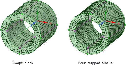
- Click Complete
 to set the
mesh type control.
to set the
mesh type control.
The Map/Sweep control can also be used to adjust mesh after it has been created. If using the Map/Sweep control with an already meshed model, use the face control to adjust the block face mesh type. For example, a free face (any mesh type), can be converted to a mapped face (any mesh type), or vice versa, in order to help with converting free blocks to swept blocks or swept blocks to mapped blocks or vice versa.
To convert a block face type, simply select the option you want to convert the block face to, and then pick the face. The block face will be converted accordingly. If in Play mode, the mesh will be updated. If in Pause mode, the mesh will not be updated until you turn on Play mode, however, you can continue converting other face types or solid block types without updating the mesh.