Creating a Match Control
- On the ribbon, click Match.
 Note: You may apply a match control to blocking faces or geometry faces. If the Ghost blocked geometry option is enabled (default) and the mesh has been generated, blocking faces will be selected. To select geometry faces instead, disable the Ghost blocked geometry option or hide the blocking in the Structure tree.
 - Click Select high faces
 ,
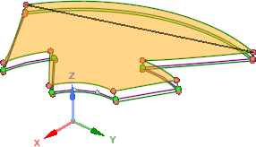
and then identify those faces from which mesh parameters are to be matched.
Selected face(s) are highlighted.
,
and then identify those faces from which mesh parameters are to be matched.
Selected face(s) are highlighted. - Click Select low faces
 , and
then identify those faces to which the parameters are to be matched. Selected
face(s) are highlighted in a contrasting color.
, and
then identify those faces to which the parameters are to be matched. Selected
face(s) are highlighted in a contrasting color. - Click Select axis of rotation
 (optional), and then select an appropriate center
of rotation for a cyclic match control. You may select a geometry edge or
curve, a created axis, or coordinate system axis.If a valid axis is selected, the Angle option value is automatically calculated from the selected faces. You may manually specify an angle value.
(optional), and then select an appropriate center
of rotation for a cyclic match control. You may select a geometry edge or
curve, a created axis, or coordinate system axis.If a valid axis is selected, the Angle option value is automatically calculated from the selected faces. You may manually specify an angle value. - If you are matching blocking, click Select a high Vertex
 , and then identify a key point on the high face, when blocking exists. You may
select a geometry point or block vertex. Blocking does not possess "direction".
This point acts like an origin point relative to the face.
, and then identify a key point on the high face, when blocking exists. You may
select a geometry point or block vertex. Blocking does not possess "direction".
This point acts like an origin point relative to the face. - If you are matching blocking, click Select a low Vertex
 , and then identify the corresponding key point on
the low face.Note: High and Low vertices may also be used to automatically compute the Angle when an Axis of rotation is identified.
, and then identify the corresponding key point on
the low face.Note: High and Low vertices may also be used to automatically compute the Angle when an Axis of rotation is identified. - Click Complete to create the Match control.You can check for matched nodes by mousing over a connected face with the Match tool active. Matched nodes are indicated with a black, double-headed arrow.