


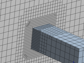
The Ansys Meshing application allows you to generate CutCell meshes, in order to reduce the time needed to mesh complex geometry. This functionality was originally developed for Ansys Fluent, but it is also compatible with Polyflow applications. The CutCell mesher converts a volume mesh into a predominantly Cartesian mesh (that is, the mesh consists of mostly hexahedral elements, with faces that are aligned with the coordinates axes). Smaller elements are used to resolve complex details of the geometry, and the interfaces between the different size elements are non-conformal (see Figure 2.1: An Example of a CutCell Mesh). Note that the Polyflow solver will reconnect adjacent elements of different discretization sizes with conformity constraints, in the same manner as the recursive subdivision of elements technique used for adaptive meshing (see the Polyflow User’s Guide).
If you want to use the CutCell meshing technique, perform the following steps in Ansys Meshing:
Select the Mesh object in the Tree Outline.
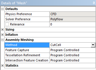
Perform the following in the Details view (Figure 2.2: The Details View for CutCell Meshing):
In the Defaults group, select CFD from the Physics Preference selection list.
Select Polyflow from the Solver Preference selection list.
In the Assembly Meshing group, select CutCell from the Method selection list.
Important: Note the following when working with CutCell meshes:
For flow applications, you must carefully check the generated mesh in order to avoid thin regions in which only one element exists between opposite walls. If such situation occurs, all velocity nodes of such elements have fixed (and generally) null values (that is, a fixed wall condition): no fluid will cross these elements, leading to artificial obstacles in the flow.
You must not combine (for example, using Ansys Polyfuse) a mesh that was generated by the CutCell method with another type of mesh, if you intend to use it in an Ansys Polyflow simulation; Ansys Polyflow requires that the mesh you read in consists of a domain in which either every part or no part is a CutCell mesh. Consequently, you cannot use an unaltered CutCell mesh with moving boundaries (for example, in a free jet region outside of an extrusion die), as the remeshing algorithms require a sliceable mesh, which is typically a swept mesh. To overcome this limitation, you can use Polydata to convert a portion of your CutCell mesh into a sliceable mesh, as described in the Polyflow User's Guide.
CutCell meshes are not compatible with mixing or volume of fluid (VOF) tasks, viscoelastic flow sub-tasks (see Ansys Fluent Meshes Created with Ansys Meshing, Ansys Fluent, and Fluent Meshing in the Polyflow User's Guide for a comprehensive list), contact detection, internal radiation, the Narayanaswamy model, flow-induced crystallization, or the adaptive meshing technique. Moreover, the interpolation for the velocity field is limited: for a pure CutCell mesh, it must be the linear element; for a portion of a CutCell mesh that has been converted into a sliceable mesh, it can be either the linear element or the mini-element.
CutCell meshes should not be used when PMeshes are also created, as the compatibility is not guaranteed.