


When creating a sliding mesh simulation, mesh each part separately, and ensure that none of the meshes connect. In the valid configuration described previously, the following three mesh regions were required:
the outer domain of the screw barrel (
SD1)the left cam (
SD2)the right cam (
SD3)
Note that edge bs5 is separate and coincident to
bs2. During the simulation, as nodes on edges
bs5 and bs2 slide past each other,
the solver will interpolate flow variables across the disconnected mesh. Specific
interface boundary conditions are required to couple sliding meshes together. Figure 23.3: The Mesh of the Surrounding Domain SD1 shows the mesh of the surrounding
domain (SD1).
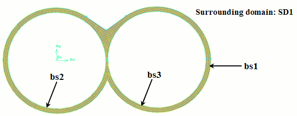
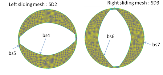
Figure 23.4: The Sliding Meshes shows the mesh of the domains
(SD2 and SD3) attached to each
moving part. It contains two internal boundaries, bs4 and
bs6, and two external boundaries,
bs5 and bs7. The internal boundary
bs2 of SD1 must be tangential to
the external boundary bs5 of SD2.
Similarly, bs3 of SD1 must be
tangential to bs7 of SD3. The element
size on both boundaries should be same for more accuracy.
In the transient simulation, rotate the mesh SD2 (or
SD3) at the same angular velocity prescribed along its
internal boundary bs4 (or bs6). Use
the non-conformal method to connect the velocity nodes of bs2
(or bs3) to the corresponding nodes of
bs5 (or bs7). For additional
information on the non-conformal method, see Non-Conformal Boundaries.
Note: The algorithm Ansys Polyflow uses to connect the boundaries is actualized at each time
step as the sliding meshes rotate. The fluid exiting SD1
enters SD2 or SD3 (or vice-versa),
and thus the total volume of the fluid is conserved. This flow rate balance is more
accurate as the mesh is refined.