This section provides two examples: one with valid configuration and the other with invalid configuration.
valid configuration
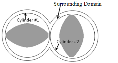
Figure 23.1: Valid Configuration for the Sliding Mesh Technique represents a valid configuration for the sliding mesh technique. Two separate cylinders (
Cylinder#1 andCylinder#2) are defined, which surround two cams. The axis of rotation of each cylinder corresponds to the axis of rotation of the cam. The union of the surrounding domain and of the two cylinders form the fluid region. You can mesh each region separately. It is not necessary to mesh the interior of moving parts.invalid configuration
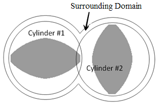
Figure 23.2: Invalid Configuration for the Sliding Mesh Technique represents an invalid configuration for the sliding mesh technique. You cannot use this technique, because the cylinders surrounding the moving parts are overlapping.