


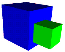
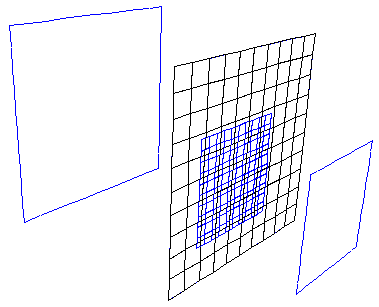
It is possible for Ansys Polyflow to compute a solution on a domain consisting of geometrically coincident but disconnected parts (for example, Figure 8.2: Domain with Geometrically Coincident but Disconnected Parts). Consider a conformal mesh to be one that reflects the continuity of the domain through element connectivity, and a non-conformal mesh to be a region meshed in different parts where the boundary regions are geometrically—but not topologically—coincident (for example, Figure 8.3: Non-Conformal Boundary Meshes).
The non-conformal boundary condition allows you to create an approximate conformity of the finite-element representation.
For complex geometries (particularly those with regions of different scales, such as the inlet region of a profile tread die), the use of non-conformal meshes can be very beneficial, since creating a conformal mesh through all parts of the simulation domain is often difficult for such geometries.
With a non-conformal mesh, it is not necessary to propagate the small elements of the "small" region to the larger (for example, inlet) zone. Note, however, that solutions on non-conformal meshes are generally less accurate than those on conformal meshes.
Important: The usage of non-conformal boundaries is limited to heat transfer cases, and isothermal and non-isothermal flows of generalized Newtonian fluids, possibly including transport of species. Non-conformal boundaries are not available for viscoelastic fluid models (including the simplified viscoelastic model).