See Figure 4.2: Subdomains and Boundary Sets for the Sample Problem to determine where each boundary is located. Select each boundary and modify its conditions as needed. Set the conditions at each of the boundaries of the domain:
boundary 1 (BS_1): flow inlet
boundary 2 (BS_2): outer wall
boundary 3 (BS_3): free surface
boundary 4 (BS_4): flow exit
boundary 5 (BS_5): symmetry axis
boundary 6 (BS_6): rotating screw
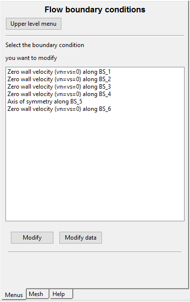
Selecting the Flow boundary conditions menu item will open the panel shown in Figure 4.15: Default Boundary Conditions.
![]() Flow boundary conditions
Flow boundary conditions