After creating an appropriate mesh in Ansys Polyfuse, follow these steps to define your problem in Ansys Polydata:
Read in the combined mesh.
 Read a mesh file
Define a time-dependent task for your problem.
Create a new task
Define a sub-task.
Create a sub-task
Select the appropriate problem type.
Important: The mesh superposition technique can be used only for a generalized Newtonian flow problem.
Generalized Newtonian isothermal flow problem
Generalized Newtonian non-isothermal flow
problem
When prompted, specify a name for the sub-task.
Specify the stationary portion of the region where the sub-task applies.
Domain of the sub-task
Here, you should choose the subdomain(s) representing the stationary part of the domain. Each of the moving parts will be defined separately, as described in the next step.
Define the moving part(s).
Define moving parts
The Define moving parts menu will open. For each moving part, perform the following steps.
Create a new moving part.
Creation of a new moving part
If your mesh is 2D, Ansys Polydata will inform you that quadratic coordinates are needed, and that the modification to quadratic coordinates has been done automatically. Ansys Polydata will define the right interpolant for velocity, pressure, and temperature when a moving part has been defined. This is taken care of properly in 3D as well, although no message appears.
Ansys Polydata will inform you that the tolerance for time marching has been increased to 10000. This is done in order to keep the time step
 constant, as discussed in Time-Dependent Parameters. You
can simply click to continue.
constant, as discussed in Time-Dependent Parameters. You
can simply click to continue. Specify the subdomain(s) representing the moving part.
Definition of the moving part domain
Define the initial position and motion of the moving part. In general, the position of the moving part in the mesh file does not correspond to its initial position for the simulation, so you will need to specify an initial position as well as the motion. The simplest case involves rotation about a fixed axis with the reference position corresponding to the initial position. A more complex case involves rotation about a moving axis with a translation, with the initial position different from the reference position. See Guidelines for Problems with Transient Velocities for guidelines on setting up the motion when the axis of rotation is moving.
Definition of the motion
To specify rotation of the moving part, choose Modify the point of local rotation axis, Modify the orientation of local rotation axis, and Modify the angular velocity. The angular velocity can be dependent upon the evolution parameter
 . (See Evolution for details about
evolution.)
. (See Evolution for details about
evolution.)Important: Note that angular velocity must be entered here in RPM. (In other places, the angular velocity is given in rad/s.)
To specify translation of the moving part, choose Modify the translation velocity. The translation velocity can be dependent upon the evolution parameter
 . (See Evolution for details about
evolution.)
. (See Evolution for details about
evolution.)If the reference position of the moving part is not the initial position, specify the initial position by choosing Modify the initial translation vector and/or Modify the initial angle of rotation. If you specify an initial angle, it must be in degrees.
If the axis of rotation is moving, specify its initial position (angles
 and
and  ) and the angular velocities
(
) and the angular velocities
( and
and  ) about the
  and
and  axes, respectively, by choosing
Modify the initial theta angle (Z
axis), Modify the initial phi angle
(Y axis), Modify angular velocity
Vtheta (Z axis), and Modify angular
velocity Vphi (Y axis).
axes, respectively, by choosing
Modify the initial theta angle (Z
axis), Modify the initial phi angle
(Y axis), Modify angular velocity
Vtheta (Z axis), and Modify angular
velocity Vphi (Y axis). The initial angles must be specified in degrees, and the angular velocities can be dependent upon the evolution parameter
 . (See Evolution for details about
evolution.)
. (See Evolution for details about
evolution.)If you would like to keep the moving part at the reference position (that is, do not change the topology or symmetry of the moving part), select Disable update of moving part coordinates.
Accept the default values for the mesh superposition technique parameters.
Superposition technique
In the Superposition technique menu, there are two parameters: the threshold coefficient and the relative compression factor. In general, there is no reason to modify the default values of these parameters.
The threshold coefficient is used to separate the nodes of the flow domain into two categories: those inside the moving part and those outside. Its default value is 0.6; nodes with a value greater than this will be inside the moving part, as discussed in Navier-Stokes Equations. Increasing the threshold will cause the finite-element representation of the moving part to be slightly thinner.
The relative compression factor (
 in Equation 22–4) has the default value of 0.01, which
should not be modified.
in Equation 22–4) has the default value of 0.01, which
should not be modified. Define the flow boundary condition along the moving part. By default, a stick condition will be applied on all the boundaries of the new moving part. To impose a partial or full slip condition, click
Flow boundary conditions
and perform the following steps:
Click Switch to slip condition.
Click Modify maximum slipping stress. You can specify a value of shear stress in the menu that opens: below this value, a full stick condition is assumed; otherwise, a slip condition is modeled with this value (and no higher value) applied. Note that a non-zero value is required for the maximum slipping stress.
For nonisothermal flows, define the thermal boundary conditions for the moving part.
Thermal boundary conditions
You have the following options:
You can have Polyflow solve a heat conduction problem for the moving part. Note that this is the default setting; if you revised the default setting, you can switch back by clicking Switch to heat conduction problem.
Switch to heat conduction problem
Next, specify the material properties for the moving part.
Material data
You must specify the Density, Thermal conductivity, and Heat capacity per unit mass of the moving part. Additionally, if your moving part is imparting heat to the flow, you will need to specify the Heat source per unit volume. After the material properties are defined, click Upper level menu to return to the moving part menu.
See Energy Equation for further details on the equations used for the heat conduction problem and the treatment of the nodes inside and outside of the moving part.
You can impose a temperature distribution on the moving part that is fixed (that is, does not change as the part moves through the flow domain).
Switch to temperature imposed condition
Next, define the temperature distribution.
Temperature distribution
In the menu that opens, you can specify that the temperature distribution is defined by: a constant value; a linear function of
 ,
,  , and
, and  coordinates; a multi-ramp function of
either
coordinates; a multi-ramp function of
either  ,
,  , or
, or  coordinates; a comma separated file (CSV)
file; or a user-defined function. Note that when the
temperature distribution is a function of the coordinates,
the coordinates used by Polyflow are those associated with
the initial position of the moving part (that is, the
position shown in the graphic display window of Polydata).
This "initial" temperature field is stored at the nodes of
the moving part.
coordinates; a comma separated file (CSV)
file; or a user-defined function. Note that when the
temperature distribution is a function of the coordinates,
the coordinates used by Polyflow are those associated with
the initial position of the moving part (that is, the
position shown in the graphic display window of Polydata).
This "initial" temperature field is stored at the nodes of
the moving part.The menu items used to define the temperature distribution are similar to those used to define the initial fluid fraction in a VOF task. See step 5.a. in Problem Setup for further details. After the temperature distribution is defined, click Upper level menu twice to return to the moving part menu.
Note that if you impose a fixed temperature distribution, the nodes of the flow domain will be affected when they are overlapped by the moving part during the simulation: the nodes of the flow domain will be treated as if they were inside the moving part, and their local temperatures will be set equal to the corresponding local temperatures in the moving part (as if they was set using the Temperature imposed boundary condition).
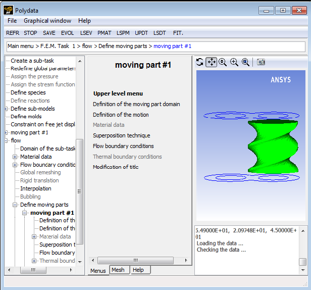
Specify the name of the moving part.
Modification of title
To modify the definition of an existing moving part, return to the Define moving parts menu, click the appropriate name, and follow the previous steps.
To delete a moving part, return to the Define moving parts menu, click the Deletion of a moving part menu item and then click the appropriate name.
Define the other parameters of the flow (material data, flow boundary conditions, thermal boundary conditions, etc.) as usual.
Define the numerical parameters for the time-dependent task (one level above the sub-task menu).
Numerical parameters
See Additional Guidelines and User Inputs for Time-Dependent Problems for details about the inputs for time-dependent calculations. If you select Modify the transient iterative parameters, you will see that the tolerance has been modified for you, as mentioned above.