Keep the following items in mind when planning and setting up a model with internal moving parts:
The meshes for the flow domain and the moving parts should contain elements of about the same size.
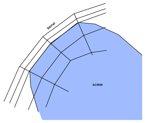
It is important that the mesh be fine enough in regions of small geometrical details; otherwise, the coarse mesh will smooth out the details. For the clearance between a screw and its barrel, at least two elements are recommended in the thickness direction (see Figure 22.8: Elements Between a Screw and its Barrel). Pressure peaks can also be generated due to a coarse mesh in the angular direction.
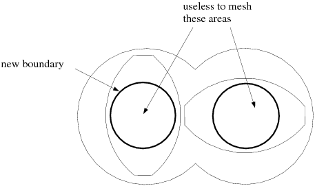
Areas covered by moving parts that are never in the real fluid region do not have to be meshed. Modifying the mesh as shown in Figure 22.9: Reducing Mesh Size will reduce its size and consequently the overall cost of the simulation.
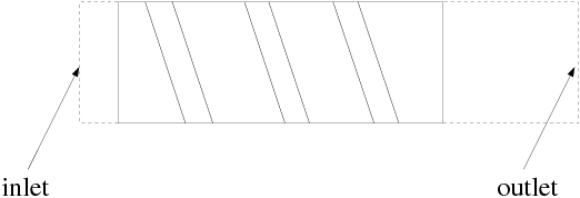
If internal boundaries are overlapped by moving parts, make sure that the boundary conditions are compatible with the motion of the moving parts. Some boundary conditions can easily become incompatible with rotating screw constraints. In particular, this may be the case when a screw is rotating and touching the entry/exit sections where an outflow or inflow condition (which implies a zero tangential velocity) is imposed. In this case, you should either extend the flow domain, as shown in Figure 22.10: Extending the Flow Domain to Avoid Incompatibilities in Boundary Conditions, or apply zero force conditions instead of outflow or inflow conditions.
Make sure that the moving parts are rotating in the right direction. For a transient simulation, it is a good idea to perform a steady-state simulation first, in order to check the direction of rotation.
Proper definition of the simulation time and the time step are very important. A time step that is too small will increase the CPU time unnecessarily.
The simulation time should be the time (
 , in seconds) required for the moving parts to come back to
their initial position, which will depend on the symmetry in the simulation:
, in seconds) required for the moving parts to come back to
their initial position, which will depend on the symmetry in the simulation: 
(22–29)
The flow will be calculated at constant time steps (that is, at constant angular steps). The number of steps (
 ) should be the number of elements crossed by the tip of the
moving parts during the time of simulation, and the time step is determined by
) should be the number of elements crossed by the tip of the
moving parts during the time of simulation, and the time step is determined by 
(22–30)