


The most commonly used remeshing techniques available in Polyflow require that the free jet domain is "sliceable". To understand what is meant by sliceable, imagine that a free jet domain is divided into a series of parallel slices that are perpendicular to the main flow direction: the first slice is the starting section of the remeshing domain, the last slice is the ending section of the remeshing domain, and the slices in between exist where there are nodes. The mesh is considered sliceable if the topology (that is, the number of nodes, segments, and faces) is identical in each slice.
A free jet domain that is not sliceable can be generated in various ways: for example, if you use the CutCell method in Ansys Meshing (in such circumstances, a non-conformal mesh is generated throughout the full mesh, and therefore also in the free jet), or if you generate a mesh containing tetrahedral or pyramids in the free jet.
For the times when you want to use a remeshing technique that requires a sliceable mesh, Polydata provides a tool that allows you to replace the mesh of the free jet region with a new sliceable mesh; as a result, you do not need to recreate a sliceable mesh in Ansys Meshing (a task that can be quite difficult). This tool can also be used to modify aspects of an existing sliceable free jet mesh, such as the level of refinement or the length of the free jet. Such a modification can be performed quickly and easily without having to use Ansys DesignModeler or Ansys Meshing.
Note: For complex simulations (for example, inverse prediction) in which the adaptive and/or constant sections are not sliceable, Polydata has remeshing techniques that do not require the domain to be sliceable. Such techniques are specified using the Adaptive section for prediction (no slice) and the Constant section for prediction (no slice) in the Remeshing technique menu (see Inverse Extrusion and Die Design for details).
To convert a mesh into a sliceable mesh or to modify an existing sliceable mesh, perform the following steps:
Read the mesh.
Select the Generate a sliceable free jet menu item in the main menu of Polydata.
 Generate a sliceable free jet
The Generate a sliceable free jet menu will open.
Specify the domain of the free jet.
Enter the free jet domain
When defining the domain, note that the following conditions must be met in order for the free jet topology to be acceptable: each sub-domain of the free jet must touch both the starting and ending sections of the free jet; furthermore, such sub-domains cannot lie along boundaries of the extrusion die.
Specify which boundaries make up the starting and ending sections of the free jet domain.
Enter the free jet boundary conditions
The starting section can each be composed of several boundaries, but all of the boundaries must lie on a single plane that has a normal aligned with a coordinate axis (X, Y, or Z). Each boundary of the starting section must have a corresponding boundary in the ending section. The ending section must be planar and parallel to the starting section. The resulting mesh will be "extruded" from the starting section in the normal direction to the ending section.
Note: Several starting boundaries can be extruded to the same boundary in the ending section. In fact, the ending section is usually a single boundary.
When defining the starting and ending sections, note that the following conditions must be met in order for the free jet topology to be acceptable: each boundary of the free jet that is not part of the starting and ending sections must connect to both the starting and ending sections of the free jet.
Specify the length of the free jet.
Modify length of the free jet
Start with a reasonable estimate of the length. You can always use this menu item in successive simulations to fine-tune the length: you can generate a longer extrudate if the resulting velocity profile is not fully uniform in the ending section, or a shorter extrudate if you do not observe any additional deformation of the free jet beyond a given distance from the die lip.
You can change the method by which the mesh is generated, as displayed in the text at the top of the Generate a sliceable free jet menu, by repeatedly clicking the Modify method of generation menu item.
Modify method of generation
The selected method determines how the thickness of the elements evolves along the extrusion direction, using parameters that are defined in later steps. Three methods are available:
uniform
For this method, the thickness of every element in the direction of extrusion will be set to the starting element thickness.
linear
For this method, the thickness of the elements will evolve linearly in the direction of extrusion from the starting element thickness, according to the following equation:

(7–8)
where
 is the thickness of the layer number
  ,
,  is the starting element thickness, and
  is the growth factor.
geometric
For this method, the thickness of the elements will evolve geometrically in the direction of extrusion from the starting element thickness, according to the following equation:

(7–9)
where
 is the thickness of the layer number
  ,
,  is the starting element thickness, and
  is the growth factor.
Specify the thickness of the first layer of elements in the free jet (adjacent to the starting section).
Modify starting element thickness
If you selected the linear or geometric method of generation in a previous step, specify the growth factor used to determine how the thickness of the elements evolves along the extrusion direction.
Modify growth factor
Specify the file name of the new mesh that will be generated by the solver.
Modify new mesh file name
By default, the file name of the new mesh is
newfrj.msh.Save your settings and generate the sliceable mesh.
If you launched Polydata from Polyman or from Ansys Workbench, click the Save and exit menu item and then run the solver.
Save and exit
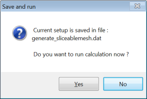
If you are using the stand-alone version of Polydata, click the Generate and exit menu item, which will open the Save and run dialog box (see Figure 7.13: The Save and run Dialog Box).
Generate and exit
Click Yes to run Polyflow immediately. In any case, a data file (named
generate_sliceablemesh.dat) will be generated for further use.
In the listing file produced by the Polyflow solver, you can follow the generation of the new mesh:
 **************************************
 *                                    *
 * Generation of a sliceable free jet *
 *                                    *
 **************************************

 Domain to remesh : free jet support.


 Starting sections :
  - (freejet*die).

 Ending sections :
  - (freejet*outlet).

 Geometric method of generation

 Free jet length :  0.5000000E+02
 Element thickness . :  0.1500000E+01 (in first layer)
 Growth factor  :  0.1200000E+01

 Nb. of layers  :     12
 Generation in Z- direction

 Saving subdomains :
   - die
   - freejet

 Saving boundaries :
   - walls
   - inlet
   - outlet
   - part_solid_1

 *** WARNING *** from [regenr]
    Distorted element has been detected.
    Element    6080 of subdomain    1
    The check of the element connectivity is skipped,
    but the conversion continues without guarantee of results.
    Warning while creating topology (part I) of the new mesh !!


 Saving new mesh in file : newfrj.msh
Note that in the previous example, a warning is displayed: a distorted element has
been found in the subdomain 1 (corresponding in this example to
the domain named die). This illustrates the fact that the
elements that are outside of the free jet domain are not altered.