


In many cases, you will want to predict the die shape required in order to obtain a desired extrudate shape, rather than predicting the extrudate shape for a particular die. This is referred to as an inverse extrusion problem.
The procedure for setting up an inverse extrusion problem is similar to the procedure for a direct extrusion problem, but the remeshing will be applied to the die in addition to the extrudate, because the die shape is unknown a priori and will be computed based on the given extrudate shape. The extrudate must be remeshed as well, because only the exit shape is known. To define an inverse extrusion problem in Ansys Polydata, follow the steps below (in conjunction with the general steps listed in General Procedure):
In the menu for the free-surface or moving-interface boundary condition, identify the outlet of the die, which is the beginning of the moving surface. This imposes a boundary condition on the free surface or moving interface, as described in step 3 in General Procedure.
 Boundary conditions on the moving surface
In the menu for free surface boundary condition, identify the exit of the calculation domain, whose shape will be considered as fixed and will be interpreted as the required extrudate shape:
Outlet (Inv. Prediction)
Usually, the outlet coincides with the exit of the calculation domain. The outlet is defined by specifying the boundary or subdomain adjacent to the free surface. It is important to note that this information is not related to the assignment of a boundary condition on the moving surface. Instead, it will be handled as a constraint on the development of the extrudate, which will be used for calculating the die shape that allows matching this constraint at the exit of the calculation domain.
Alternatively, the outlet for inverse prediction can also be defined via the Global remeshing menu as indicated below under item 3(b).
Define the inverse prediction in the Global remeshing menu.
Inverse prediction management
Turn on the inverse prediction.
Enable the inverse prediction
Important: You must define an outlet for each free surface and moving interface. Otherwise, Ansys Polydata will issue a warning when you try to save the data file.
Define the outlet of the free surface or moving interface.
Free surface along boundary/subdomain x
or
Interface along boundary/subdomain x
You will define the outlet in the same way as the inlet, by specifying the adjacent boundary or subdomain. The outlet will be the intersection of the free surface or moving interface with the specified boundary or subdomain.
Note that you can also specify the outlet using the Outlet (Inv. prediction) item in the menu for the free-surface or moving-interface boundary condition.
Create a new local remeshing area (or select the first one), and select the subdomain(s) that represent the part of the die for which Ansys Polyflow has to compute the shape (referred to as the adaptive section of the die), based on the specified extrudate shape.
1-st local remeshing
This will allow the mesh to adapt between the constant entry section of the die and the die lip section, as Ansys Polyflow calculates the die lip profile that produces an extrudate of the prescribed shape.
Select Adaptive section for prediction or Adaptive section for prediction (no slice) in the Remeshing technique menu.
Adaptive section for prediction
Adaptive section for prediction can be chosen when the mesh of this section can be "sliced". This can be done if the mesh in this section is semistructured, that is, along the direction of extrusion, it is made of a series of successive "slices", all slices being topologically identical (same number of nodes, segments and faces). In such a case, the adaptive section will be deformed by applying homothetic transformations of various amplitudes on the slices.
Adaptive section for prediction (no slice)
Adaptive section for prediction (no slice) should be chosen when the mesh in this section is unstructured (for example, a mesh made of tetrahedra). In such a case, this section will be deformed using an elastic technique.
When prompted, indicate the beginning (inlet) and end (outlet) of the adaptive section by specifying the intersection with the appropriate adjacent boundary or subdomain. See Figure 15.14: Typical Inverse Extrusion Problem and Figure 15.15: Modeling Approaches for the Problem in Figure 15.14: Typical Inverse Extrusion Problem
Ansys Polyflow will adapt the mesh linearly between the fixed inlet section and the die exit (which is remeshed using Optimesh or streamwise remeshing).
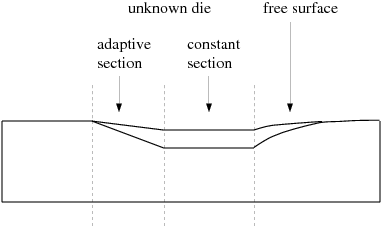
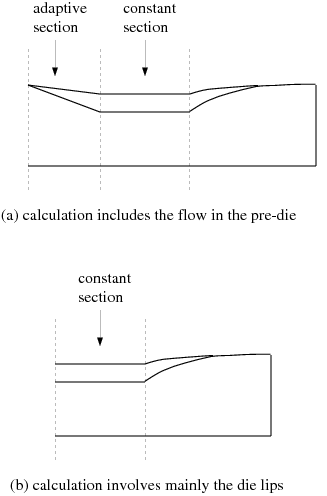
Figure 15.15: Modeling Approaches for the Problem in Figure 15.14: Typical Inverse Extrusion Problem
There are occasions when a complex geometry and the required flow conditions create complications while setting up an inverse extrusion problem using the no slice remeshing technique. For instance, you may have bodies that are not to be used in the problem setup, or you may have inadvertently assigned a wall boundary that intersects with an inlet.
For an inverse extrusion problem that uses the no slice (or non-sliceable) remeshing technique for the deformation of the die, consider the following limitations:
While you can have an inlet condition for the inlet section of a die deformation, or have an intersection with an upstream non-deformable body (that is used in the simulation), you cannot combine these conditions.
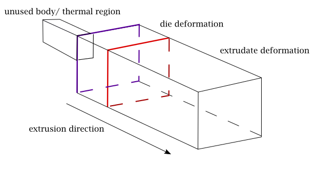
You cannot have an unused body or a thermal region in contact with the die deformation.
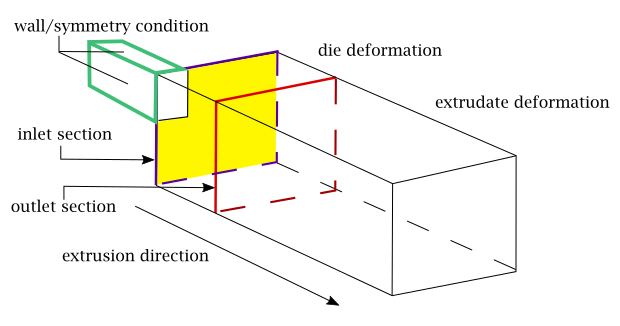
You cannot have a wall condition or a symmetry condition partially or totally in the inlet section. That is, you cannot have a portion of the inlet section (in yellow in the following figure) where a wall condition could be defined.
The outlet section should contain only the faces at the intersection of the die deformation and the extrudate deformation objects.
The inlet and the outlet sections must be roughly perpendicular to the extrusion direction.
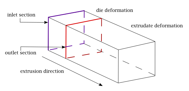
For the die deformation, any surface that is not in the inlet section or the outlet section, is referred to as a lateral boundary.
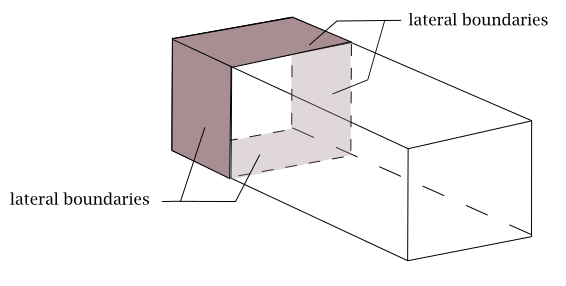
To correctly set up the problem, you need to define enough lateral flow and/or symmetry conditions. The lateral conditions must be split into different boundary conditions, so that each condition is defined on a surface that has four bounding lines:
One source line, intersecting the inlet section,
One target line, intersecting the outlet section,
Two generation lines (starting on the inlet section and ending on the outlet section).
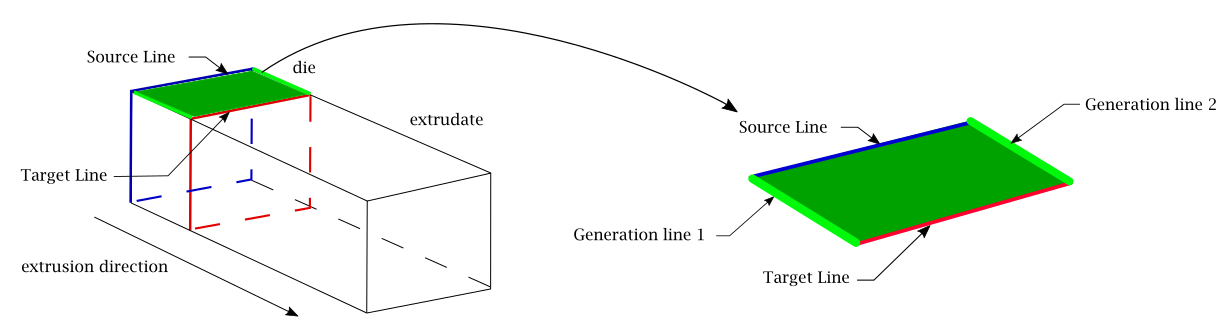
Note: You must define at least three lateral, non-overlapping boundary conditions.
Ansys Polyflow implicitly assumes that the shape of the inlet and outlet sections are very similar (ideally, they should initially overlap) and the finite element faces of the lateral boundaries are perpendicular to the direction of extrusion. Also note that Ansys Polyflow performs a check to see if the lateral faces have an angle greater than 60° with the direction of extrusion.
If the non-sliceable technique cannot be easily employed in an inverse extrusion problem setup, due to a sufficiently complicated geometry, you can try to simplify the geometry appropriately, and use the sliceable technique.
If problems arise during the setup and solution of problematic scenarios, refer to the following table for relevant messages you might encounter, and the recommended actions you can perform.
| Message | Recommended Action |
|---|---|
|
The inlet and outlet sections must not come into contact with each other. |
Make sure that the inlet section does not come into contact with the outlet section. |
|
A lateral boundary is not in contact with either the inlet section or the outlet section. |
Make sure the inlet section and the outlet section each are in contact with all lateral boundaries. |
|
Several lateral boundaries are not in contact with either the inlet section or the outlet section. | |
|
There are not enough lateral boundaries: define at least three lateral boundaries. |
Make sure that you have defined at least three lateral boundaries. |
|
A lateral boundary is in contact with more than two other lateral boundaries. |
Make sure that each lateral boundary is in contact with two other lateral boundaries. |
|
Several lateral boundaries are in contact with more than two other lateral boundaries. | |
|
One lateral boundary is in contact with only a single other lateral boundary, or none at all. |
Make sure that each lateral boundary is in contact with two other lateral boundaries. |
|
Several lateral boundaries are in contact with only a single other lateral boundary, or none at all. | |
|
The inlet and outlet sections are not parallel. |
Make sure that the inlet section is more or less parallel with the outlet section. |
|
One lateral boundary contains faces that are not properly oriented with respect to the direction of the extrusion. |
Make sure that lateral boundary faces are more or less parallel with the direction of the extrusion. |
|
Several lateral boundaries have faces that are not properly oriented with respect to the direction of the extrusion. |
To maintain the die lip shape over a given length in the direction of extrusion, define two local remeshing areas: one for the adaptive section of the die, and one for the constant section. To maintain the section at a constant shape, select Constant section for prediction or Constant section for prediction (no slice) instead of Adaptive section for prediction or Adaptive section for prediction (no slice).
![]() Constant section for prediction
Constant section for prediction
As with Adaptive sections, Constant section for prediction can be chosen when the mesh of this section can be "sliced". In such a case, the constant section will be deformed by applying homothetic transformations of the same amplitude on all of the slices. In additon, you must specify the beginning (inlet section) and the end (outlet section) of the Constant section for prediction.
![]() Constant section for prediction (no slice)
Constant section for prediction (no slice)
Constant section for prediction (no slice) should be chosen when the mesh in this section is unstructured (for example, a mesh made of tetrahedra). In such a case, this section will be deformed using an elastic technique.