The steps for defining a film model are listed below:
Define a sub-task for the film model.
 Create a sub-task
Select the appropriate problem type.
Film model: Gen. Newtonian isothermal
Film model: Gen. Newtonian non-isothermal
Film model: Viscoelastic isothermal
Film model: Viscoelastic non-isothermal
When prompted, specify a name for the sub-task.
Specify the region where the sub-task applies.
Domain of the sub-task
(nonisothermal flows only) Set the general parameters of the material.
Material data
The two items in this menu are Average temperature and Heat source per unit volume. The latter is constant, while the former can be constant, or a linear function of mesh coordinates.
Define the flow boundary conditions.
Flow boundary conditions
See Flow Boundary Conditions for guidelines, and Boundary Conditions for general information on boundary conditions.
Define the thermal boundary conditions (nonisothermal flows only).
Thermal boundary conditions
See Boundary Conditions and Problem Setup for details. See also Thermal Boundary Conditions for specific information for film problems.
If you want to model the effect of heating or cooling air onto the film surface, select Surface Heat source in the Thermal boundary conditions panel.
Surface Heat source
This will bring up a menu in which you can define the surface heat flux parameters
 and
and  described in Heating and Cooling of the Film.
Select a remeshing rule.
Global remeshing
For information on remeshing, including descriptions of available remeshing rules, see Remeshing.
Modify the interpolation scheme (optional).
Interpolation
See Controlling the Interpolation for information on interpolation in generalized Newtonian flows, and Selecting the Interpolation for viscoelastic flows. See General Procedure for information on interpolation in nonisothermal flows.
Define the layers of the film.
Define layers
Follow these steps to define a new layer.
Select Creation of a new layer.
Define the physical properties for this layer (viscosity, density, etc.).
Material data
Each layer can have distinct physical properties.
Set the boundary conditions for this layer.
Thickness boundary conditions
By default, Ansys Polyflow specifies no boundary conditions for the film thickness.
Select the side along which a thickness boundary condition will be imposed and click Modify.
Select Thickness imposed and specify film thickness as a constant, as a linear function of coordinates, or by means of a UDF.
Set the initial thickness for this layer.
Initial thickness
The initial thickness of the film layer is used for initializing the unknown corresponding field. Usually, it is reasonable to use an average value of the specifications you employed when defining the Thickness boundary conditions. The initial thickness of the film layer can be set in one of four ways:
As a Constant. You must specify a value that will be the initial thickness over the entire fluid layer.
As a Linear function of coordinates. Here, you will specify three values
 ,
,  , and
, and  (in 2D) to define the thickness as
(18–8)
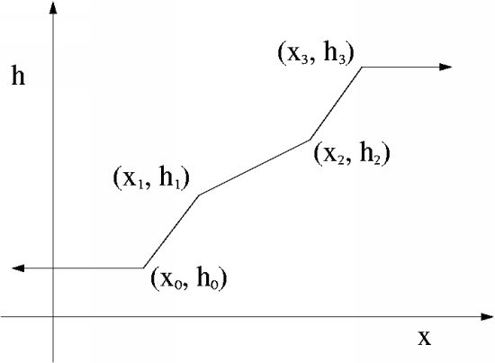
As a Multi-ramp function of
 or
or  . You will enter a sequence of pairs
 (or
(or  as appropriate) that defines the thickness
as a piecewise linear function (see Figure 18.2: Example of a Multi-Ramp Function for an example).
as appropriate) that defines the thickness
as a piecewise linear function (see Figure 18.2: Example of a Multi-Ramp Function for an example).Select Define new pairs and enter data pairs when prompted.
Select Check existing pairs to check your inputs.
To modify an incorrect pair, select Modify mode and then select the pair to be modified.
To delete an incorrect pair, select Delete mode and then select the pair to be deleted.
The set of points you enter can be saved for future use using the Save in a Dependence Data File menu item, and recalled later with the Read in a Dependence Data File menu item.
Instead of interactively entering the data for the multi-ramp, the data can be read from a file, where the pairs of data must be written with the fixed (Fortran) format 2e14.7. This means that each pair of data (
 ,
,  ) is written on a single line, and fourteen
digits are used for representing each data as
) is written on a single line, and fourteen
digits are used for representing each data as
 0.1234567e
  89. Since the format is fixed, there is no
need to use a separator. For a single data, the format e14.7
successively involves: a sign, a 0 digit, the decimal dot,
seven digits (for the mantissa), the letter "e" standing for
a power of 10 eventually given by its sign and the last two
digits. In such a format, -
89. Since the format is fixed, there is no
need to use a separator. For a single data, the format e14.7
successively involves: a sign, a 0 digit, the decimal dot,
seven digits (for the mantissa), the letter "e" standing for
a power of 10 eventually given by its sign and the last two
digits. In such a format, -  is then represented as -0.31415926e+01. If
an entry (
is then represented as -0.31415926e+01. If
an entry ( ,
,  ) in the file consists of (0.25,-
 ), for example, it will be represented as
+0.2500000e+00-0.31415926e+01. Subsequent pairs of data are
written on subsequent lines.
), for example, it will be represented as
+0.2500000e+00-0.31415926e+01. Subsequent pairs of data are
written on subsequent lines. From data in a CSV (Excel) file. In this case, values to be specified as a boundary condition are defined in a comma separated values (CSV) file, in a way similar to that described in Results Interpolation Onto Another Mesh for specifying data on the whole domain. Ansys Polydata will prompt you for the name of the CSV file, as well as the case-sensitive tag used to identify the data for this boundary condition. Correspondence between mesh nodes and data points is not required; Ansys Polyflow will interpolate the data to the mesh nodes.
For the DCPP model, set the inlet stress for the layer.
Enable stress condition
By default, the anisotropy direction is along the X axis, the anisotropy factor is 0, while the stretching scalar is 1. This can be changed when needed.
Switch to Y for direction of stretching
By selecting this option, the anisotropy will be defined with respect to the
 direction.
Modify value of anisotropy factor
direction.
Modify value of anisotropy factor
By selecting this option, you can modify the anisotropy factor s in the direction defined previously. Any value between 0 and 1 is valid. If
 (isotropic), all three components of the
orientation tensor are set to
(isotropic), all three components of the
orientation tensor are set to  ; if
; if  , we have a 100% orientation along the selected
direction of anisotropy and therefore a unit value for the
corresponding component of the orientation tensor, while the other
components vanish.
Modify value of stretching
, we have a 100% orientation along the selected
direction of anisotropy and therefore a unit value for the
corresponding component of the orientation tensor, while the other
components vanish.
Modify value of stretching
By selecting this option, you can modify the stretching amplitude in the direction defined previously. Any positive value is valid. However, recommended values should be at least equal to unity; values lower than unity are of course permitted, but would probably not match the physics in the die.
(optional) Give the layer a name. By default, all layers are simply called new layer.
Modification of title
To modify the definition of a layer you have already created, select its name from the Define layers menu and follow the steps above.
To delete a layer, select the Deletion of a layer menu item and then choose the layer to be deleted.