


For a film problem, boundary conditions for the velocity should typically be set as follows:
A uniform normal velocity profile should be specified at the inlet to the computational domain, while a take-up velocity or force should be imposed at the exit, together with a vanishing tangential force.
For the two lateral sides, two free surfaces or one free surface and one line of symmetry should be defined. The free surface condition requires additional data (see Free Surfaces and Extrusion for information on defining free surfaces). Briefly, a fixed point for the free surface, and possibly some constraint on the directors should be specified. Also, it is usually advised to enable the upwinding for the kinematic equation on the free surface(s).
As an example, consider the computational domain displayed in Figure 18.1: Example of Flow Boundary Conditions for Film Casting.
It is important to note here that the velocity on the take-up roll usually differs from the entrance velocity by a factor of between 10 and 50. To get the problem to converge, the velocity at the exit is increased using an evolution scheme (see Evolution), starting from a rigid body translation problem, and evolving to the actual stretching problem.
In multilayer film flow problems, the various layers are overlapping on the same computational domain. Therefore, no interface boundary conditions are needed between layers. Continuity conditions are automatically satisfied in the model because of the unique definition of the velocity and temperature fields.
For viscoelastic flow problems, set the boundary conditions for the velocity field, but not for the extra-stress tensor. The solution will produce a stress field that is still in equilibrium according to the momentum equation, although additional data should be specified for the hyperbolic constitutive equation. However, the effect of not prescribing this part of the extra-stress tensor has very minor effects on the solution itself.
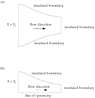
For nonisothermal film flow problems, a temperature should typically be imposed at the inlet to the computational domain, as displayed in Figure 18.3: Example of Thermal Boundary Conditions for Film Casting, while no heat exchange is assumed along the other boundary segments.
In a multilayer film problem, several layers will overlap the same computational domain. However, no interface boundary conditions are needed between layers, since continuity conditions are automatically satisfied by the model, in view of the definition of an average temperature field. In particular, this is compatible with the basic assumption that there are no temperature variations throughout the thickness of the film.
Suggested boundary conditions for the viscoelastic variables of the DCPP model can only be defined along the side that is selected for thickness boundary conditions. Imposing boundary conditions for the viscoelastic unknowns (orientation and stretching) is optional. If conditions are imposed, you will need to provide the following information:
the direction of anisotropy of the orientation tensor (
 or
or  )
) the anisotropy factor ranging between 0 (isotropic) and 1 (anisotropic)
the inlet stretching
By default, the anisotropy direction is along the X axis, the anisotropy
factor is 0, while the stretching scalar is 1. This corresponds to a situation
where the melt has not undergone deformation in the die before being extended.
Actually, the flow in a die is dominated by shear, which may certainly affect
the orientation tensor, while stretching will remain close to unity. Therefore,
a typical inlet boundary condition for film casting would involve a nonzero
anisotropy factor and a unit stretching. You can change this according to your
needs. On the basis of the value entered for the anisotropy direction and
anisotropy factor  , the value of the orientation tensor S at the inlet can be
evaluated and assigned as:
, the value of the orientation tensor S at the inlet can be
evaluated and assigned as:
 | (18–9) |
where  is the selected direction of anisotropy,
  is perpendicular to it in the plane of the film; and the
component
is perpendicular to it in the plane of the film; and the
component  . If
. If  (isotropic), all three components of S are set to
 ; if
; if  (100% anisotropy), we have
  , while the other components vanish. Any value between 0 and 1
is valid. For the stretching variable, it is recommended that the values should
be at least equal to unity; values lower than unity are of course permitted, but
would probably not match the physics in the die. When a multilayer system is
defined, inlet boundary conditions can be defined independently for each layer,
as is already the case for the thickness. In the case of multi-mode model for a
given layer, all modes will undergo the same selected inlet conditions. Finally,
it is worth mentioning that the solver exhibits better performances when
reasonable inlet boundary conditions are selected for the viscoelastic unknowns
of the DCPP model in film casting.
, while the other components vanish. Any value between 0 and 1
is valid. For the stretching variable, it is recommended that the values should
be at least equal to unity; values lower than unity are of course permitted, but
would probably not match the physics in the die. When a multilayer system is
defined, inlet boundary conditions can be defined independently for each layer,
as is already the case for the thickness. In the case of multi-mode model for a
given layer, all modes will undergo the same selected inlet conditions. Finally,
it is worth mentioning that the solver exhibits better performances when
reasonable inlet boundary conditions are selected for the viscoelastic unknowns
of the DCPP model in film casting.