You can apply deformation methods on surfaces that act as the boundary conditions of a 3D domain on which the elastic remeshing method has been applied. You have the following options for deforming or moving surfaces:
no constraints on surface
The "no constraints on surface" method does not apply an equation on the surface. The coordinates of the nodes belonging to the surface are governed by the equations applied on the 3D domain that contains the surface.
elastic remeshing
For the "elastic remeshing" method, the motion of the nodes is governed by Equation 35–3. The pseudo-elastic equation defined on the surface replaces the 3D equation for the interior nodes of the surface. This equation requires boundary conditions, which can be selected from the line transformations described in Line Transformations.
planar elastic remeshing
The "planar elastic remeshing" method can only be applied on a flat surface, and the methods applied on its borders must induce deformations that will stretch the surface without any torsion (that is, the surface must remain flat). The motion of the nodes is governed by Equation 35–3, coupled with the constraint on the normal displacement shown in Equation 35–4. The pseudo-elastic equation defined on this surface will replace the 3D equation for the interior nodes of the surface. This equation requires boundary conditions, which can be selected from the line transformations described in Line Transformations.
sliceable ruled surface
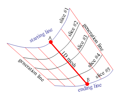
The "sliceable ruled surface" method can be applied when you want the interior nodes to move along a ruled surface, which is initially defined between two lines (referred to as the "starting line" and the "ending line"). For this method to be appropriate, the mesh related to the surface must meet the following conditions:
All the nodes on the mesh must align in straight lines between the nodes of the starting and ending lines. Note that the straight lines on the edges of the surface can be referred to as "generation lines".
The mesh must be made up entirely of quadrilateral elements. The edges of the quadrilateral elements must be able to be grouped into "slices" that cut across the generation lines, where each slice has the same number of segments.
See Figure 35.4: An Example of a Sliceable Ruled Surface for an example of a sliceable ruled surface. The surface can be open (that is, having 4 boundaries, as shown in Figure 35.4: An Example of a Sliceable Ruled Surface), or closed (for example, a tube). For closed surfaces, there are only two boundaries: the starting and the ending lines.
The surface can be described as a set of 1D meshes, where each of these meshes is made of segments that start from a node (A) on the starting line and end on a corresponding node (B) on the ending line. The motion of the nodes along these 1D meshes is governed by the pseudo-elastic equation (Equation 35–3). You define the starting line, and set up boundary conditions on the starting and ending lines using the line transformations described in Line Transformations.
In the cases where there are several adjacent sliceable ruled surfaces, you must ensure that the surfaces are oriented appropriately. For details, see Remarks and Limitations.
ruled surface
The “ruled surface" method can be applied when you want the interior nodes to move along a ruled surface, which is initially defined between two lines (referred to as the "starting line" and the "ending line"). For this method to be appropriate, the mesh related to the surface must meet the following conditions:
The surface must have four boundary lines, (that is, it cannot be a closed surface, like a tube). The two opposing boundary lines referred to as the starting and ending lines may be curved, while the other two opposing lines (called the "generation lines") must be straight.
All the nodes of the mesh must be located directly between a point on the starting line and a point on the ending line.
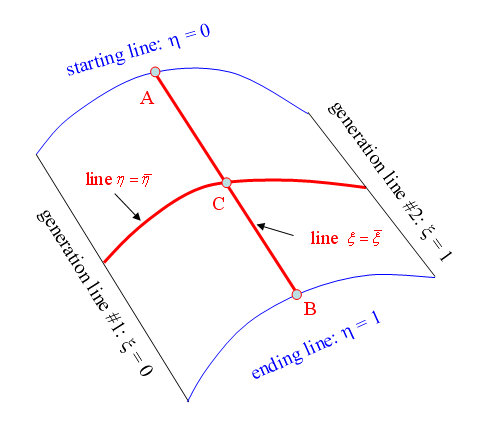
While the ruled surface method shares some similarities with the sliceable ruled surface described earlier, there are some differences. First of all, the ruled surface is not restricted to meshes that are composed entirely of quadrilateral elements. Secondly, the surface is not converted into a set of 1D meshes. Instead, the nodes are constrained to only move along imaginary lines that begin on the starting line and end on the ending line. To generate these imaginary lines, a local coordinate system (
 ,
,  ) is created for the surface (see Figure 35.5: An Example of a Ruled Surface). The
  coordinate varies linearly along the surface from
generation line #1 (where
coordinate varies linearly along the surface from
generation line #1 (where  ) to generation line #2 (where
  ). The
  coordinate varies linearly along the surface from the
starting line (where
coordinate varies linearly along the surface from the
starting line (where  ) to the ending line (where
  ). During the mesh deformation, each node (for example, C) on the
surface of a given local coordinate (
). During the mesh deformation, each node (for example, C) on the
surface of a given local coordinate ( ,
,  ) is moved in order to stay on a straight line (for example, line
AB) where
) is moved in order to stay on a straight line (for example, line
AB) where  , and on the curved line where
  . Linear interpolation is used to determine the movement of
the node, rather than the pseudo-elastic equation.
. Linear interpolation is used to determine the movement of
the node, rather than the pseudo-elastic equation. You define the starting line, and set up boundary conditions on the starting and ending lines using the line transformations described in Line Transformations.
In the cases where there are several adjacent ruled surfaces, you must ensure that the surfaces are oriented appropriately. For details, see Remarks and Limitations.
rigid translation
For the "rigid translation" method, the motion of the nodes is governed by Equation 35–2. This method is applied on all topological entities included in the domain definition (that is, lines and points). Hence, it is not possible to apply another motion on these entities when defining the deformation of an adjacent domain.
fixed surface
For the "fixed surface" method, the motion of the nodes is governed by Equation 35–1. As a result, all the nodes of the surface remain fixed at their original coordinates. This method is applied on all topological entities included in the domain definition (that is, lines and points). Hence, it is not possible to apply another motion on these entities when defining the deformation of an adjacent domain.
symmetry
For the "symmetry" method, a flat plane is treated as a plane of symmetry. In other words, the surface is deformed due to the methods applied on its borders, with the constraint that the nodes remain in the original plane. The motion of the nodes is governed by the elastic remeshing method applied on the 3D domain, with the constraint on the normal displacement shown in Equation 35–4. Note that the selection of the symmetry method for the surface transformation does not define the flow as being symmetrical about this surface, as the two conditions are not linked.