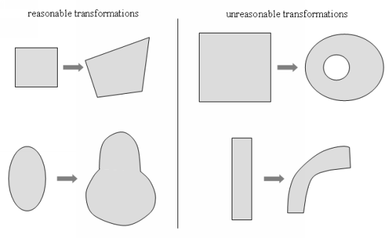
The mesh deformation techniques described in the previous section are intended to result in reasonable deformations of the mesh. A reasonable deformation requires that the topology remain almost the same, with the same number of domains and same number of boundaries. It is not possible, for example, to start from a square and obtain a circle with a hole inside. Figure 35.11: Reasonable and Unreasonable Mesh Transformations depicts examples of reasonable and unreasonable deformations.
Some considerations when evaluating the reasonableness of a deformation include the following:
Geometric entities cannot be rotated.
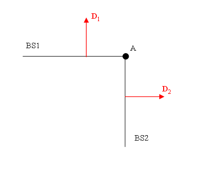
It is not possible to impose two independent rigid translations on two adjacent entities, as shown in Figure 35.12: An Example of an Invalid Setup for Rigid Translations D1 and D2 . In this example, a rigid translation with
 is imposed on BS1, while another rigid translation with
 is imposed on BS2. Such a circumstance leads to a conflict for
the direction at point A.
is imposed on BS2. Such a circumstance leads to a conflict for
the direction at point A. Directions can only be given as constant values, and it is not possible to define them using an evolution parameter, a UDF, or a UDT.
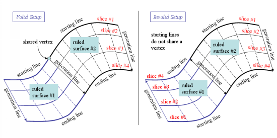
You must make sure that adjacent ruled surfaces (sliceable or not) are oriented the same way. For example, Figure 35.13: Adjacent Ruled Surfaces Connected at Generation Lines illustrates the case when two adjacent ruled surfaces share a generation line. To ensure a compatible orientation, you must select their starting lines so that they share a vertex.
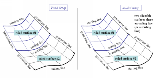
Figure 35.14: Adjacent Ruled Surfaces Connected at Ending / Starting Lines depicts another possible configuration with adjacent ruled surfaces, in which they share a starting and/or ending line. In this situation, you must make sure that the starting line of one of the surfaces corresponds to the ending line of the adjacent surface. In this manner, both surfaces are oriented in the same way.
It is a common practice to perform an initial simulation with a coarse mesh in order to test a model; if the simulation is successful, this same setup is then used with a more refined mesh. You must exercise caution, however, when attempting such a procedure if you defined methods of mesh deformation using control points. Ansys Polyflow references control points by their vertex ID, therefore if you alter the mesh without updating the data file, the vertex IDs will point to vertices other than the ones you expect. As a result, the mesh will deform in an unexpected manner. In order to avoid such a circumstance, always be sure to load your data file in Ansys Polydata with your new mesh. Ansys Polydata will automatically update the data structure in the following ways:
For vertices that are at the extremities of lines, the vertex IDs will be updated such that the new vertex IDs correspond exactly to the same line extremities.
For vertices that are included in a line (corresponding to added control points), the vertex IDs will be updated such that the new vertex IDs correspond to the closest vertex on the same line.
You should check if the closest vertex selected by Ansys Polydata corresponds well with the defined setup (for example, direction of displacement); if not, you can select another vertex on the line. When you have reviewed any questionable vertices, you can save and exit Ansys Polydata. It is recommended that you save the data file with a new name, in order to distinguish it from the original data file.