


This multi-part tutorial shows how to use named selections in these scenarios:
Note: You cannot change the reference named selection after field data objects are added to the database. Field data objects are always defined on a reference named selection. By default, oSP3D uses the entire reference mesh.
oSP3D recognizes and imports named selections within the reference mesh.
To start a new project and set a reference mesh and named selections within the reference mesh:
Set up the project:
Start a new oSP3D project.
For Filename, select the mesh file sos_mesh.cdb in
oSP3D_examples\ansys\simple_cube.For Project name, set a name of your choice.
Set the named selection:
Select > > .
For nodes used for statistics/models, set the named selection SOS_MODEL_NODES.
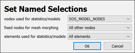
All field data objects of the node type, such as field designs, models, and statistics results, are defined on this reference named selection.
Click .
Create a synthetic random field model:
Select > > .
For Ident, set an identifier of your choice.
For Data type, select Node.
Click .
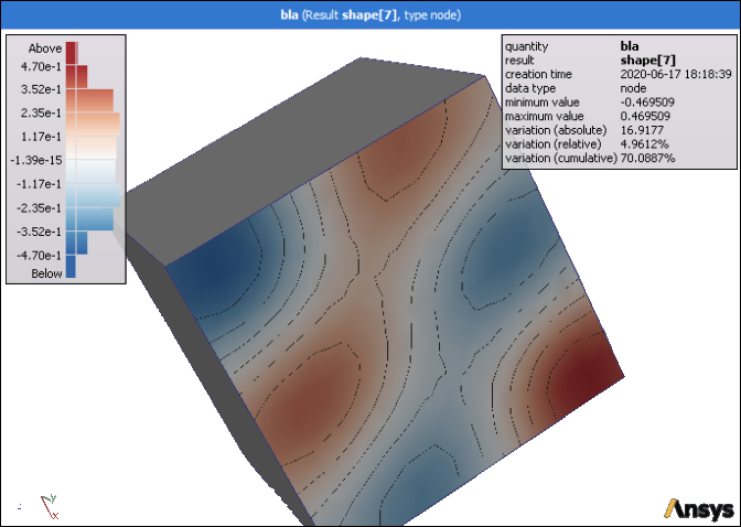
You can now visualize a shape of the newly created random field model.
This image shows a random field model defined on a reference named selection of type node.
To start a new project, set a reference mesh, and import named selections from a CSV file:
Set up the project:
Start a new oSP3D project.
For Filename, select the mesh file sos_mesh.cdb in
oSP3D_examples\ansys\simple_cube.For Project name, set a name of your choice.
While this mesh file contains named selections, you can still add your own named selections from a CSV file.
Import the named selection from the CSV file:
Select > > .
Open the file named_selection.csv in
oSP3D_examples\ansys\simple_cube\named_selections.This file contains a list of element and node identifiers.
For Ident, set an identifier of your choice.
For Data type, select Element set.
Click .
oSP3D interprets the CSV file as a list of element or node Identifiers, depending on selected data type.
Set the imported named selection:
Select > > .
For elements used for statistics/models, set the imported named selection.
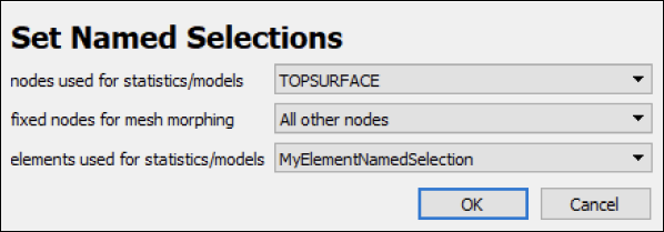
All field data objects of the element type, such as field designs, models, and statistics results, are defined on this reference named selection.
Click .
Create a synthetic random field model:
Select > > .
For Ident, set an identifier of your choice.
For Data type, select Element.
Click .
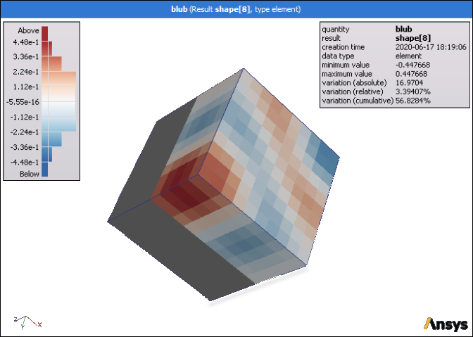
You can now visualize a shape of the newly created random field model.
This image shows a random field model defined on a reference named selection of type element.
To start a new project, import named selections, and set a fixed boundary for mesh morphing:
Set up the project:
Start a new oSP3D project.
For Filename, select the mesh file sos_mesh.cdb in
oSP3D_examples\ansys\simple_cube.For Project name, set a name of your choice.
While this mesh file contains named selections, you can still add your own named selections from a CSV file.
Import named selections from a CSV file:
Select > > .
Open the file bottom_and_one_side.txt in
oSP3D_examples\ansys\simple_cube\named_selections.For Ident, set an identifier of your choice.
For Data type, select Node set.
Click .
Import and set more named selections:
Import named selections from the file top_surface.txt in
oSP3D_examples\ansys\simple_cube\named_selections as a Node set.For nodes used for statistics/models, set the named selection TopSurface.
For fixed nodes for mesh morphing, set the named selection BottomAndOneSide.
For elements used for statatistics/models, set All elements.
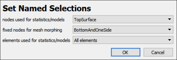
Click .
Create a synthetic random field model:
Select > > .
For Ident, set an identifier of your choice.
For Data type, select Node
For Standard deviation, select Define homogeneous and set the value to 0.002.
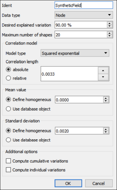
Click .
Visualize the morphed mesh:
In the Choose visible data toolbar, select Contour plot, Node data, SyntheticField, and Random field.
Click .
In the Choose visible data toolbar, select Normal displacement, Node data, SyntheticField, and Random field.
Click .
In the Field data model inspector, use the sliders to adjust the palette bounds as necessary, observing how the mesh is morphed according to the synthetic random field.
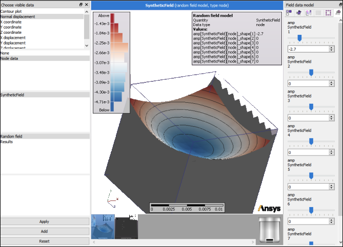
The mesh is morphed on the fly when adjusting the normal displacements according to the random field. The nodes of the named selection TopSurface that was set for nodes used for statistics/models are being morphed while the nodes of the named selection BottomAndOneSide that was set for fixed nodes for mesh morphing remain in place.
This shows that when these two named selections "touch" each other, morphing partially fails, resulting in broken mesh elements. Remember to always maintain nodes that are not part of any reference named selection between the fixed and morphed named selections.