


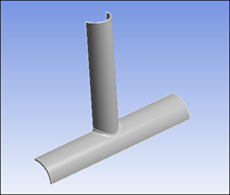
In this tutorial, a semi-elliptical crack is inserted at the tubular joint of the structure. The crack mesh is generated on the defined crack and fracture parameters based on Stress Intensity Factors (SIFS) are computed and post-processed.
| Analysis Type | Fracture |
| Features Demonstrated | Importing geometry, nodal Named Selections, coordinate systems, crack definition, fracture results, charting |
| Licenses Required | Ansys Mechanical Enterprise/Enterprise Solver/Enterprise PrepPost |
| Help Resources | Fracture Analysis, Defining a Semi-Elliptical Crack |
| Tutorial Files | Fracture_xjoint.zip |
This tutorial guides you through the following topics:
Establish a static structural analysis.
Start Ansys Workbench.
From the Toolbox, drag a Static Structural system onto the Project Schematic.
Import the model.
In the Static Structural schematic, right-click the Geometry cell and select Import Geometry > Browse.
Browse to open the file X_Joint.agdb. This file is available here on the Ansys customer site.
Prepare the analysis in Mechanical.
In the Static Structural schematic, right-click the Model cell, and then choose Edit. Mechanical opens and displays the model.
As needed, orient the model as shown below.
From the Tools group of the Home tab, open the Units drop-down menu and select .
In the Outline, right-click the Mesh object and select > .
In the Geometry window, select the body.
In the Details view, for Geometry, click Apply.
For Method, select Tetrahedrons.
This method is required for crack mesh generation.
Select the Mesh object.
In the Details, under Defaults, set the Element Size property to 20 mm and under Sizing, set the Span Angle Center property to Fine.
On the Graphics Toolbar, select the Face selection option.
In the Outline, right-click the Mesh object and select > .
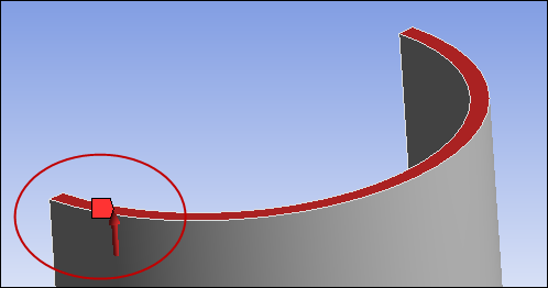
In the Geometry window, select the external filet show below.
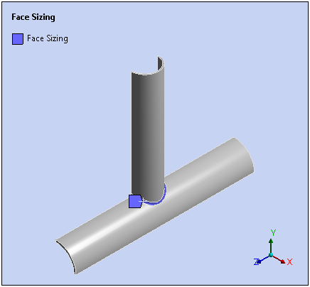
In the Details view, for Geometry, click Apply.
For Element Size, enter 5 mm.
Right-click the Mesh object and select Generate Mesh.
In the Outline, right-click the Coordinate Systems object and select >.
In the Geometry window, select the vertex lying at the center of the filet face.
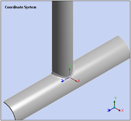
In the Details view of the new Coordinate System, select the Geometry property field and then click .
Under the Principal Axis category, set the Axis property to X and the Define by property to Hit Point Normal.
In the Geometry window, click at the origin location of the coordinate system.
In the Details view for the Hit Point Normal property, click Apply.
Insert a Fracture object into the Outline by right-clicking the Model object and selecting Insert > Fracture.
Insert a Semi-Elliptical Crack object into the Outline by right-clicking the Fracture object and selecting Insert>Semi-Elliptical Crack.
From the Graphics Toolbar, select the Body selection option.
In the Geometry window, select the body.
In the Details view, for the Geometry property, click Apply.
Specify the Coordinate System property with the coordinate system just defined.
In addition, set the following options in the Details view:
Major Radius = 18.4 mm
Minor Radius = 9.5 mm
Largest Contour Radius = 2 mm
Crack Front Divisions = 35
Circumferential Divisions = 16
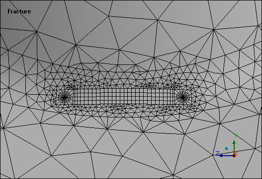
In the Outline, right-click the Fracture object and select Generate All Crack Meshes.
Zoom in on the external filet to see the generated crack mesh.
In the Outline, select the Static Structural object.
Right-click the object and select > .
In the Geometry window, select the top face as shown below.
In the Details view, for Geometry, click Apply.
For Magnitude, enter -1000 MPa. The negative value indicates the pressure direction is upward.
Solve.
In the Outline, under Static Structural, select Analysis Settings.
Under the Solver Controls category, set the Weak Springs property to Program Controlled.
Under Fracture Controls category, set the Fracture property to On (as needed), and set the Material Force and T-Stress properties to Yes.
Select the Solve option.
Define results items.
Right-click the Solution object and select Insert > Fracture Tool.
In the Details view, for the Crack Selection property, select Semi-Elliptical Crack.
Right-click the Fracture Tool folder and select > > .
Also add SIFS (K3), J-Integral (JINT), Material Force (X Axis), Material Force (Y Axis), Material Force (Z Axis), and T-Stress results.
Right-click the Fracture Tool object and select Evaluate All Results.
View results.
Select each result and view the results in the Geometry window.
View the Graph window for each result. The graph plots the stress intensity factors against the curvilinear abscissa of the crack front, starting from the origin extremity.
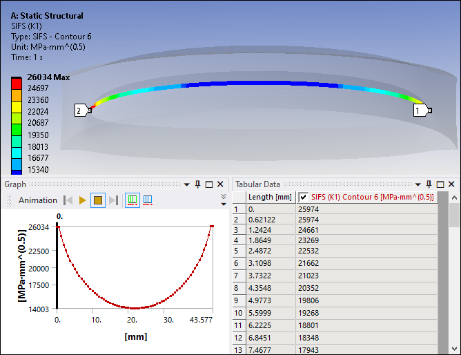
The Mode I stress intensity factor (SIFS [K1]) dominates in this scenario because the fracture surface normal is nearly aligned with the tensile load. The SIFS (K2) and SIFS (K3) results show that Mode II and Mode III contribute slightly.
Congratulations! You have completed the tutorial.