


This tutorial computes fracture parameters (energy release rates) using the Virtual Crack Close Technique (VCCT) on a static structural analysis.
| Analysis Type | Fracture |
| Features Demonstrated | Meshed model, nodal Named Selections, coordinate systems, crack definition, Virtual Crack Close Technique (VCCT) , fracture results, charting |
| Licenses Required | Ansys Mechanical Enterprise/Enterprise Solver/Enterprise PrepPost |
| Help Resources | Fracture Analysis, Defining a Pre-Meshed Crack |
| Tutorial Files | 3d_vcct |
This tutorial guides you through the following topics:
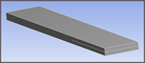
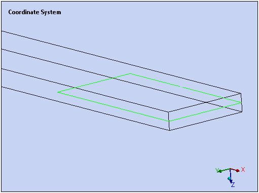
The Double Cantilever Beam shown below is cracked at the center. This problem uses an imported model, already meshed, and computes fracture parameters (energy release rates) using the Virtual Crack Close Technique (VCCT) on a static structural analysis. This will determine the impact of a catastrophic failure to the structure.
Start Ansys Workbench.
From the Toolbox, under Component Systems, drag a External Model system onto the Project Schematic.
Right-click the cell and select .
On the External Model tab, select the option in the Location column and then select . Browse to open the file 3d_vcct. This file is available here on the Ansys customer site.
Select the Data Source row for your file. In the Definition category of the properties pane (lower portion of the window), make sure that Metric (kg, m, s, °C, A, N, V) is specified.
Return to the Project tab.
Right-click the cell and select .
From the Toolbox, drag a Static Structural system onto the Project Schematic.
Drag the Setup cell of the system on to the Model cell of the Static Structural system.
Right-click the Model cell of the Static Structural system and select Refresh.
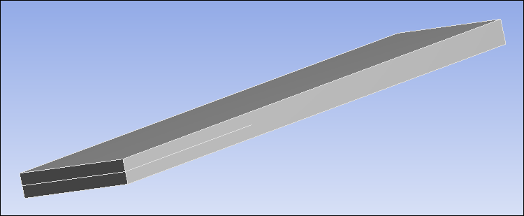
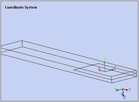
Right-click the Model cell and select Edit. Mechanical opens and displays the model. Note that the mesh is composed of linear elements, and VCCT is only applicable to linear elements. Orient the model as shown below.
From the Graphics Toolbar, select the Edge selection option and the Wireframe display option.
In the Outline, right-click Model object and select Insert>Named Selection.
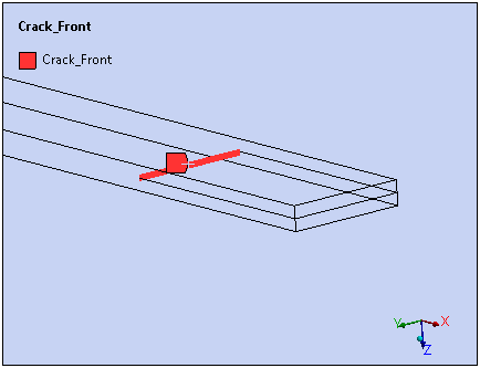
In the Geometry window, select the crack front edge.
In the Details pane, for Geometry, click Apply. The Named Selection is created for the selected edge.
In the Outline, under Named Selections, right-click the new Named Selection, select Rename, and enter
Crack_Frontas the name.Right-click the Crack_Front Named Selection and select Create Nodal Named Selection.
In the Outline, under Named Selections, right-click the new Named Selection, select Rename, and enter
Crack_Nodesas the name.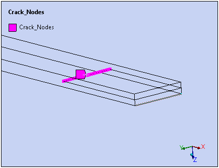
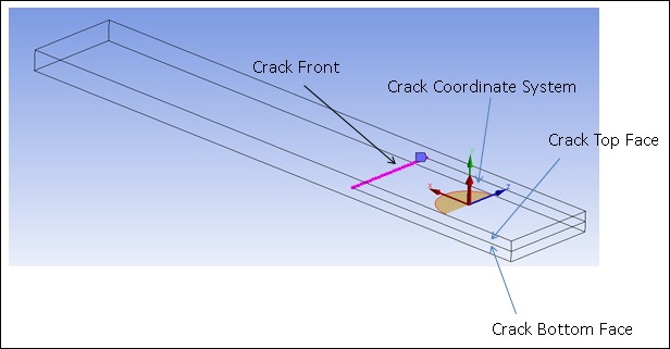
Create a Coordinate System with a Y-axis Aligned to Crack Normal
In the Details view, select Coordinate System.
In the Geometry window, select the fours edges lying in the plane of the crack.
Right-click and select Insert > Coordinate System. The origin of the coordinate system should be on the open side of the crack.
In the Details view, for Geometry, click Apply.
Under the Principal Axis category, set the Axis property to Y and the Define by property to Global Z Axis.
From the Coordinate System Context menu, select the option in the group to rotate the Y axis by -90°.
Accept all other values at their defaults.
Right-click the Model object and select Insert > Fracture.
Right-click the Fracture object and select Insert > Pre-Meshed Crack.
In the Details View, for Crack Front (Named Selection), select the Crack_Nodes node-based Named Selection.
For Coordinate System, select the coordinate system you defined.
Select the Static Structural object, right-click, and select Insert>Fixed Support.
from the Graphics Toolbar, select the Face selection option.
In the Geometry window, select the face on the closed side of the crack.
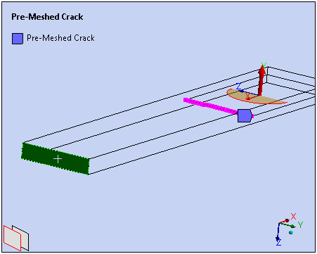
In the Details view, for Geometry, click Apply.
Right-click and select Insert>Displacement.
In the Graphics Toolbar, select the Edge selection option.
In the Geometry window, select the top edge on the open side of the crack.
In the Details view, for Geometry, click Apply.
Select the Z Component and select Tabular.
In the second row (2), for Z[m], enter
-5.e-003.Right-click and select Insert>Displacement.
In the Geometry window, select the bottom edge on the open side of the crack.
In the Details view, for Geometry, click Apply.
Select the Z Component and select Tabular.
In the second row (2), for Z[m], enter
5.e-003.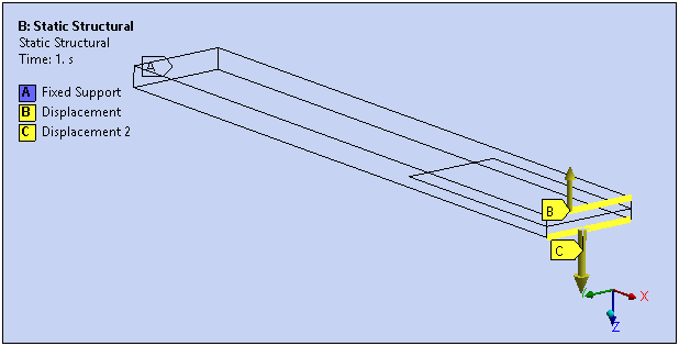
Define results.
In the Outline, right-click the Solution object and select Insert > Fracture Tool.
In the Details view for the Crack Selection property, select Pre-Meshed Crack.
Right-click the Fracture Tool folder and select > > VCCT (G1).
Also add the VCCT (G2), VCCT (G3), and VCCT (GT) results.
Solve.
In the Outline, under Static Structural, select Analysis Settings.
Under the Fracture Controls category, make sure that the Fracture property is set to On.
Click Solve.
View results.
Select each result and view the results.
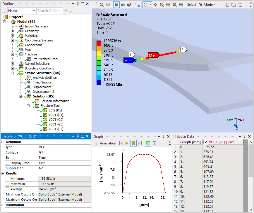
View the Graph window for each result. The graph plots the distance of the crack front node from the origin and the energy release rate as it moves along the crack front.
Since the load applied on the crack faces is tensile, the Mode I energy release rate ((VCCT (G1) ) ) dominates in this case. The VCCT(G2) and VCCT(G3) results are approximately zero. The total energy release rate (VCCT (GT) ) is approximately equivalent to VCCT(G1)
Congratulations! You have completed the tutorial.