This example problem demonstrates the use of a Rigid Dynamics analysis to examine the behavior of a track-roller mechanism using point on curve joints. The center point of an offset roller is placed directly onto a track edge to demonstrate the offset positioning capabilities of point on curve joints. While this model may not be entirely realistic, it clearly demonstrates the capabilities of the features highlighted.
| Analysis Type | Rigid Dynamics |
| Features Demonstrated | Point on curve joints, reference coordinate system, mobile coordinate system |
| Licenses Required | Ansys Mechanical Premium/Enterprise/Enterprise PrepPost |
| Help Resources | Point on Curve Joint |
| Tutorial Files | track_roller_mechanism.zip |
This tutorial guides you through the following topics:
Prepare the analysis system.
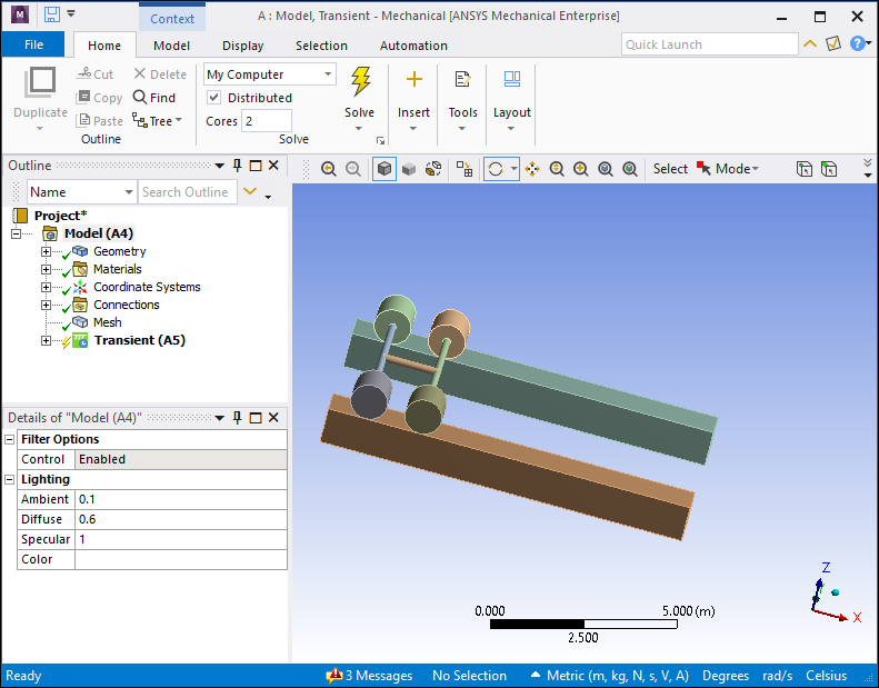
Browse to open the file TrackRoller.wbpz. A Rigid Dynamics system will populate the Project Schematic. This file is available here.
Right-click the Model cell, and select to open the Mechanical Application. The model shown below will open.
Insert a new joint.
In the Outline view, right-click the Joints folder under the Connections node, then select >.
Select the new joint in the Outline to display the joint Details view.
In the Definition section of the Details view, click the Connection Type field. The field becomes active.
Select from the Connection Type drop-down menu.
Click the Type field. The field becomes active.
Select from the Type drop-down menu.
Scope the new point on curve joint.
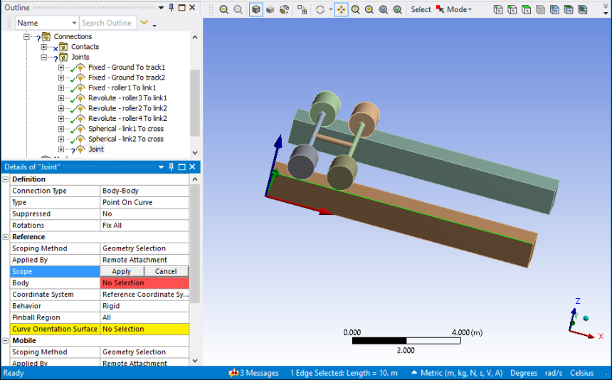
Use the edge selection tool to select an edge of the track to be used as the curve in the new point on curve joint, as shown below.
In the Details view, click to activate the Reference Scope field.
Click .
Use the face selection tool to select the face of the track to be used as the curve orientation surface, as shown below.
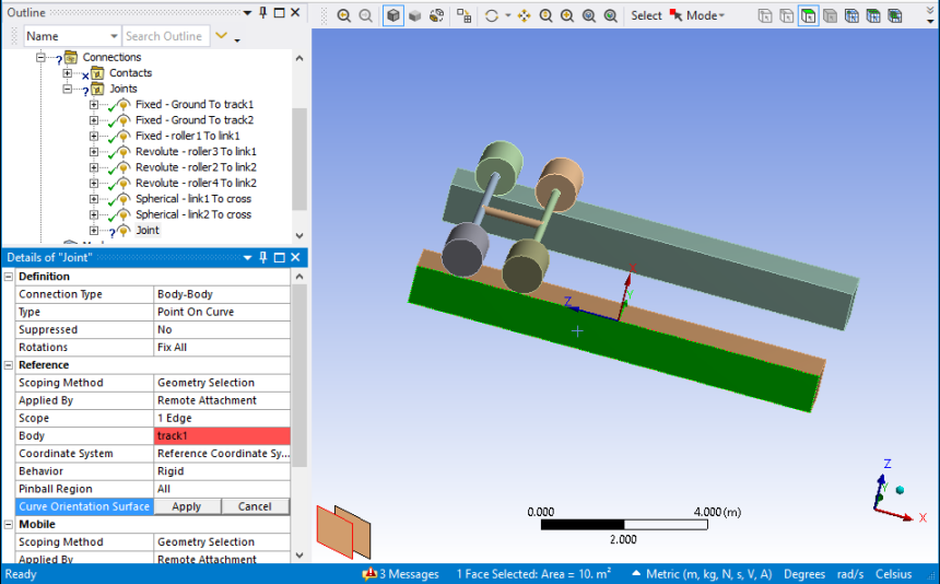
In the Details view, click to activate the Reference Curve Orientation Surface field.
Click .
In the Details view, click to activate the Reference Coordinate System field.
Configure the orientation of the reference coordinate system so that Z is the normal of the curve orientation surface and X is in the tangent of the curve. The correct orientation is show below.
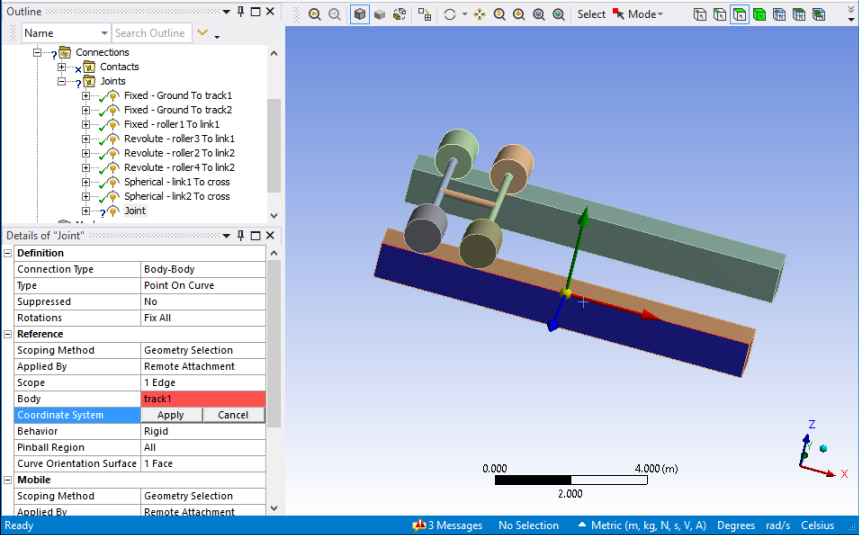
Click .
Select and configure the point used in the point on curve joint.
In this example, the center of the first roller (the circle selected below) will be selected as the point for the first joint. When creating a point on curve joint, the center of a selected geometric entity (that is, a vertex, an edge, a surface, or a volume) is considered as the point. To specify a point:
Use the edge selection tool to select the outer edge of the roller, as shown below.
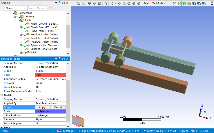
In the Details view of the joint, click to activate the Mobile Scope field.
Click .
In the Details view, click to activate the Mobile Initial Position field.
Select from the Initial Position drop-down menu.
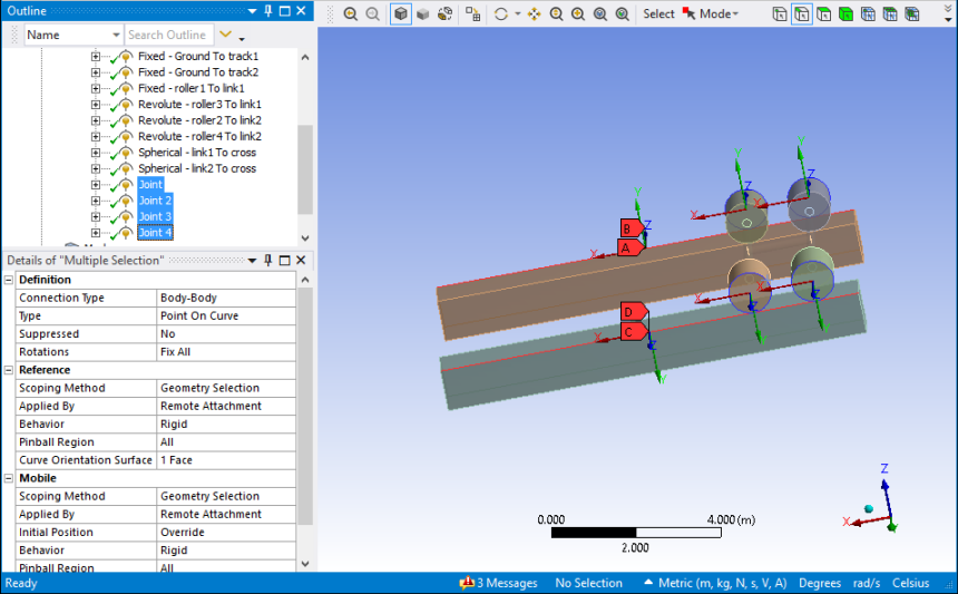
The option is necessary because the center point of the roller is offset from the track edge. If the Initial Position value of the mobile coordinate system is left to the default value, Unchanged, the reference coordinate system and mobile coordinate system are assumed to be coincident.
The center of the roller face will be used as the origin in this model. The orientations of the reference coordinate system and mobile coordinate system must be the same, or the point on curve joint will not work properly. To define the mobile coordinate system:
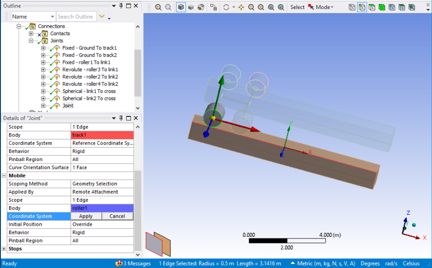
In the joint Details view, click to activate the Mobile Coordinate System field.
Select the edge of the roller using the edge selection tool. By default, this will configure the mobile coordinate system so that is corresponds to the reference coordinate system.
Ensure that both coordinate systems align as shown below, then click .
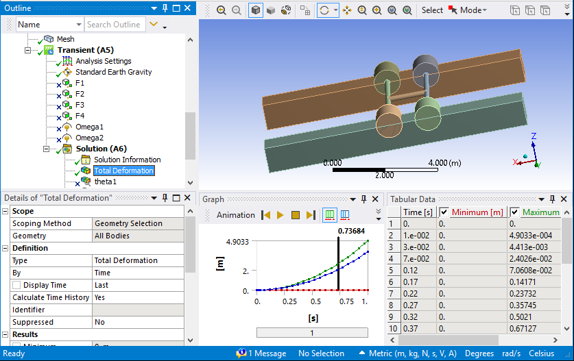
Create three more point on curve joints, one for each additional roller, and define them in a similar manner as described in Define the First Point on Curve Joint through Solve and Review the Results. Be sure to select a different roller edge (as described in 4) for each additional joint. The completed model and coordinate systems should be configured as shown in the model below.