VM-LSDYNA-SOLVE-028
VM-LSDYNA-SOLVE-028
2D Taylor Cylinder Impact
Overview
| Reference: |
Taylor, G.I. (1948). The use of flat ended projectiles for determining yield stress, part I: Theoretical considerations. Proceedings of the Royal Society (London). 194 (1038), 289-299. https://doi.org/10.1098/rspa.1948.0081 Lacy, J.M., Novascone, S.R., Richins, W.D., & Larson, T.K. (2008). A method for selecting software for dynamic event analysis II: The Taylor anvil and dynamic Brazilian tests. Proceedings of the 16th International Conference on Nuclear Engineering. INL/CON-08-13727, Idaho National Laboratory. https://digital.library.unt.edu/ark:/67531/metadc902615/m2/1/ high_res_d/940073.pdf |
| Analysis Type(s): | Explicit Dynamics 2D |
| Element Type(s): | Shell |
| Input Files: | Link to Input Files Download Page |
Test Case
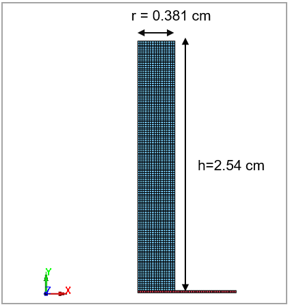
The Taylor cylinder impact test uses a right circular cylinder of a test material which impacts a theoretically rigid target. In this test, an OFHC copper cylinder, 0.762 cm in diameter and 2.54 cm in length, impacts a rigid plate at 19000 cm/s. The simulation time is 8x10⁻⁵ s. The deformed cylinder after impact will be compared with the modeled results from reference.
This test case also appears in the Workbench Verification Manual. See VM-EXD-MECH-003.
| Material Properties | Geometric Properties | Loading |
|---|---|---|
|
Cylinder material: Copper |
Diameter of cylinder = 0.762 cm Length of cylinder = 2.54 cm | Impact velocity = 19000 cm/s |
Analysis Assumptions and Modeling Notes
The cylinder and rigid plate are modeled with symmetric shell element elform 15. The rigid plate is modeled with MAT_RIGID and its x, y, z displacements and rotations are constrained by setting CON1=7 and CON2=7. The cylinder is modeled with MAT_JOHNSON_COOK with similar material properties given in the references. Equation of state (EOS) is employed for the cylinder. CONTACT_2D_AUTOMATIC_SURFACE_TO_SURFACE is applied between the cylinder and rigid plate during impact.
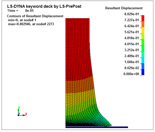
Results Comparison
The final cylinder profile is similar to the profile shown for the Autodyn results shown in the code comparison reference. The cylinder radius in the impact plane agrees well with the experimentally obtained values as well as with other simulation programs. The final cylinder length in this simulation is greater than that of the experimental value, but it agrees well with the length calculated by the other simulation programs using the same material model for copper. Figure 104 shows the final deformed copper cylinder at the end of the simulation.