VM-LSDYNA-SOLVE-029
VM-LSDYNA-SOLVE-029
Heat Transfer from a Cooling Spine
Overview
| Reference: |
Kreith, F. (1976) Principles of heat transfer (3rd ed.). Harper and Row. p.59: equation 2-44a. p.60: equation 2–45. |
| Analysis Type(s): | Linear Static Thermal Analysis |
| Element Type(s): | Solid |
| Input Files: | Link to Input Files Download Page |
Test Case
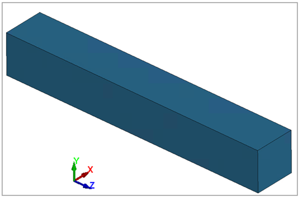
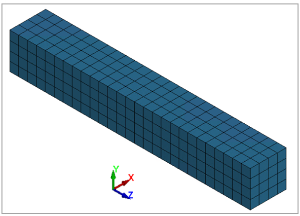
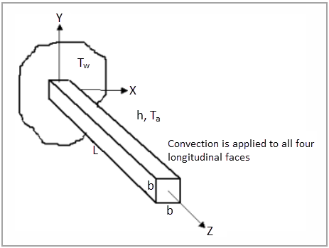
A steel cooling spine of cross-sectional area A and length L extend from a wall that is maintained at temperature Tw. The surface convection coefficient between the spine and the surrounding air is h, the air temperature is Ta, and the tip of the spine is insulated. Advanced mesh control is applied with element size of 0.025'. Figure 105 shows the external forces and supports for each case. The goal is to find the heat conducted by the spine and the temperature of the tip.
This test case also appears in the Workbench Verification Manual. See VM-WB-MECH-008.
| Material Properties | Geometric Properties | Loading |
|---|---|---|
|
E = 4.177 x 10⁹ psf ν = 0.3
Thermal conductivity k = 9.71 x 10⁻³ BTU/s ft °F |
Cross section = 1.2" x 1.2" L = 8" |
Tw = 100°F Ta = 0°F h = 2.778 x 10⁻⁴ BTU/s ft2°F |