


*NODE
Defines nodes. All the parameters are obtained from mesh definitions of the model.
Card
NID = ID of the node.
X = x coordinate.
Y = y coordinate.
Z = z coordinate.
*ELEMENT_BEAM
Specifies beam elements.
Card
EID = ID of the element.
PID = ID of the part it belongs to.
N1 = ID of nodal point 1.
N2 = ID of nodal point 2.
N3 = ID of nodal point 3, used for cross section orientation.
*ELEMENT_SHELL
Specifies three, four, six and eight noded shell elements.
Card
EID = ID of the element.
PID = ID of the part it belongs to.
N1 = ID of nodal point 1.
N2 = ID of nodal point 2.
N3 = ID of nodal point 3.
N4 = ID of nodal point 4.
N5-8 = ID of mid side nodes for six and eight noded shells.
*ELEMENT_SHELL_THICKNESS_OFFSET
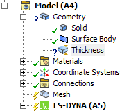
Surface body thicknesses properties can be defined on faces of surface bodies using the Thickness object in the Geometry . This keyword defines scoped surface body thickness.
Card1 - the same as *ELEMENT_SHELL
Card2
THIC1 = Thickness field of the Thickness object.
THIC2 = Thickness field of the Thickness object.
THIC3 = Thickness field of the Thickness object.
THIC4 = Thickness field of the Thickness object.
Card3
OFFSET = value calculated from the Offset Type field
of the Thickness object. if Offset Type =
Middle, it equals zero.
Top, it is equal to half of the thickness as a negative number.
Bottom, it is equal to half of the thickness.
User defined, it is equal to the value defined in the field Membrane offset .
*ELEMENT_SHELL_COMPOSITE_OFFSET
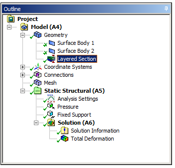
The Keyword *ELEMENT_SHELL_COMPOSITE_OFFSET allows the definition of material properties, thickness and orientation angle per thickness IP on an element basis and is used in support of ACP ply based modeling. This keyword is written in the context of layered sections. Layered section properties can be defined on faces of surface bodies using the Layered Section object in the Geometry .
The first card is identical to *ELEMENT_SHELL.
Card2
OFFSET: value calculated from the Offset Type field.
If offset type is set to Middle, it equals to zero.
If offset type is set to Top, it equals to half of the thickness as a negative number.
If offset type is set to Bottom, it equals to half of the thickness.
If offset type is set to User defined, it is equal to the value defined in the field Membrane offset.
Card3
Defines the property of two layers. Card3 is repeated as many times as required to specify all the layers in the section. The sequence is starting with the bottommost layer.
MID1: ID of material in Layer1. Must be unique between the material keyword definitions.
THICK1: Thickness of Layer1.
B1: Angle defined in the worksheet for Layer1 projected onto the element surface.
MID2: ID of material in Layer 2. Must be unique between the material keyword definitions.
THICK2: Thickness of Layer2.
B2: Angle defined in the worksheet for Layer2 projected onto the element surface.
*ELEMENT_SOLID
Specifies 3D solid elements including 10-noded tetrahedrons (second order). Apart from the second order case the two cards are combined into one.
Card1
EID = ID of the element.
PID = ID of the part it belongs to.
Card2
N1 = ID of nodal point 1.
N2 = ID of nodal point 2.
N3 = ID of nodal point 3.
N4 = ID of nodal point 4.
.
.
.
N10 = ID of nodal point 10.
*ELEMENT_SPH
Define a lumped mass element assigned to a nodal point (if the value is negative then the value is assigned to the particle volume).
Card
NID: Node ID and Element ID are the same for the SPH option.
PID: Part ID to which this node (element) belongs.
MASS (or VOLUME):
If positive: Mass value.
If negative: Volume. The density (rho) will be retrieved from the material card defined in PID. SPH element mass is calculated by abs(MASS) × ρ.