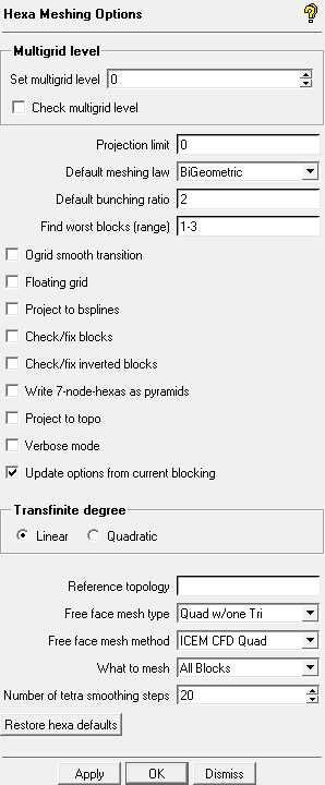
The option allows you to specify settings for hexa meshes.
- Multigrid level
allows you to create a linear multigrid mesh with a specified number of levels. The node count is altered so that the number of elements on an edge is divisible by 2^M, where M is the number of multigrid levels. Thus, the new number of nodes will be:
where N is the current number of nodes.
You must select Blocking > Pre-Mesh Params > Update Sizes to for the change to take effect on a blocking with existing node distributions, or set this parameter before prescribing node counts or element sizes.
- Check multigrid level
edges will be highlighted (red) if changing the multigrid level will change their number of nodes.
- Projection limit
controls the projection of nodes. If the Projection limit is set to a non-zero value, P, the nodes along an edge within distance P of the end of the edge will not be projected. Instead, they will be linearly interpolated between the first point farther than P and the end. Nodes on the interior of a face within distance P of the edge of the face will not be projected. Instead, they will be linearly interpolated from the interior of the face. If the Projection limit is set to 0, all nodes will be projected.
The Projection limit is set to a non-zero value in cases where you want to keep the nodes on the edges and avoid projection to the underlying surfaces. This option is typically used for Navier-Stokes grids where the grid spacing is small relative to the geometry tolerance. Allowing nodes within a gap in the geometry to project would skew the elements. With a value P set to slightly larger than the gap, the nodes would instead be interpolated. The value may have to be set by trial and error depending on skewness or negative determinants being reported by pre-mesh quality checks.
- Default meshing law
specifies the default meshing law used for node distributions for edges. Edges which have a meshing law set will retain their current law unless Blocking > Pre-Mesh Params > Update Sizes is applied.
- Default bunching ratio
specifies the default node expansion ratio along an edge from either end of the edge.
Note: Though the settings are saved in the
.aienv_optionsfile, some settings such as the bunching ratio and the meshing law may also be saved in the blocking file. If a blocking file is loaded, it will override the settings saved in the settings file.- Find worst blocks (range)
specifies the range of Worst Blocks displayed by the Find Worst blocks option.
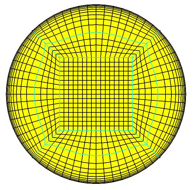
- Ogrid Smooth Transition
provides a smooth transition from the offset layer to interior layers. This option uses transfinite interpolation to prevent intermediate unprojected Ogrid splits from adversely affecting the smoothness of the mesh.
In the following figure, the cyan-colored Ogrid edge split, between the outer perimeter and the inner square, is not shaped for optimal mesh quality.
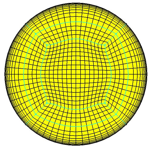
This second figure shows the central Hgrid portion and the Ogrid split has been interpolated (shaped) to more smoothly transition the mesh across the model.
- Floating grid
is used when grid distribution on faces is independent of the sub-edge structure. It also helps to turn on this option if a series of block splits have been made where the splits do not extend through the whole topology. With this option, subsequent splits would not "connect" to previous non-extended splits.
- Project to Bsplines
projects the mesh to the true Bspline geometry rather than the faceted representation, which is the internal triangulated representation of surface data as defined by Settings > Model > Triangulation Tolerance. This can be used instead of decreasing the tri-tolerance or using projection limit, where small gaps in the faceted representation create skewed elements on a Navier-Stokes grid. This, however, takes longer and more memory to compute the pre-mesh.
- Check/Fix Blocks
checks the internal block data structures for inconsistencies and fixes them if possible.
- Check/Fix Inverted Blocks
checks for all the inverted (left-handed) blocks and redefines the block by reordering the vertices to make it right-handed.
- Write 7-node-hexas as pyramids
when enabled (by default this option is disabled), converts degenerate 7-noded-hexas (2 nodes merged along an edge) into two pyramids when you select the Convert to Unstruct Mesh option under in the Model tree or when using the option.
- Project to topo
when enabled, allows a hexa face to be projected to an underlying surface. Default is off meaning the hexa face will be projected to a face family.
When two surfaces are very close to each other and highly curved, family based projection may cause the nodes to jump between surfaces.
- Verbose mode
displays additional minor warning messages that are intended to aid development or support in diagnosing possible problems that may occur. This option is disabled by default, but warnings intended to help the user with errors or problems are always displayed.
- Update options from current blocking
when enabled, this option allows the previously saved hexa settings to be overwritten by the settings from the loaded blocking file. When disabled, the previously saved hexa settings will be retained and the settings in the loaded file will be ignored. This option is enabled by default.
- Transfinite degree
Transfinite interpolation is used for face interpolation when computing a mesh. The default is linear but quadratic is better for maintaining initial element heights. The drawback is that it can produce inverted elements in bowtie-shaped blocks where linear would work fine.
- Reference topology
specifies the name of another blocking topology that you can use to test different smooth mesh options. The next time you re-compute the premesh, node positions will be matched to those in the reference topology.
For example, you set a reference topology based on a smoothed Euler mesh. If you now modify the mesh to have Navier Stokes spacing while maintaining the blocking topology, the node positions in the NS elements will match those in the smoothed Euler elements, giving you a smooth mesh but with the NS spacing.
Note: The current topology must match the reference topology exactly.
Tip: A reference topology (the basis for the smoothed mesh) can be created easily by right-clicking on > and selecting in the Display tree. Select all visible blocks and apply an appropriate name. Node locations do not get saved to the blocking file so this is available only in the current session.
- Free face mesh type
specifies the default mesh type that will be used for meshing unstructured 2D surface blocking. The following options are available:
Quad w/one Tri
Tri (STL like)
All Tri
All Quad
Quad Dominant
- Free face mesh method
specifies the method that will be used for meshing unstructured 2D surface blocking. The following options are available:
ICEM CFD Quad
GAMBIT Pave
Auto
- What to Mesh
specifies the entities or blocks to mesh for Blocking Tree > Pre-Mesh. Used typically for blocks with a mixture of mapped (structured), swept, and free (fully unstructured) 3D blocks as encountered using Multizone techniques.
- Vertices
not used.
- Edges
will mesh only edges to create line elements.
- Faces
will mesh only faces and edges to create surface mesh.
- Struct & Swept Blocks
will mesh mapped (structured) and swept blocks, but not free (unstructured) blocks.
Note: This option can be used with multizone blocking to more efficiently iterate and improve the surface mesh and boundary layers. The All Blocks option can then be used to mesh the unstructured regions also.
- All Blocks
will mesh all blocks. This is the default. Any unstructured (free) blocks will be filled with tetras using the Delaunay algorithm which could take some time for large volumes such as in external flow models.
- Number of Tetra Smoothing steps
specifies the number of Tetra smoothing steps for Multizone unstructured blocks. You may want to lower this during early iterations of Multizone blocks in order to save time.
- Restore Hexa Defaults
restores the hexa meshing settings to the defaults.