The Set Up Periodicity option allows you to define periodicity.
- Define Periodicity
ensures that the nodes line up from one periodic face to another.
Tip: Periodicity can be set for both Tetra and Hexa meshes.
- Rotational periodic
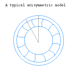
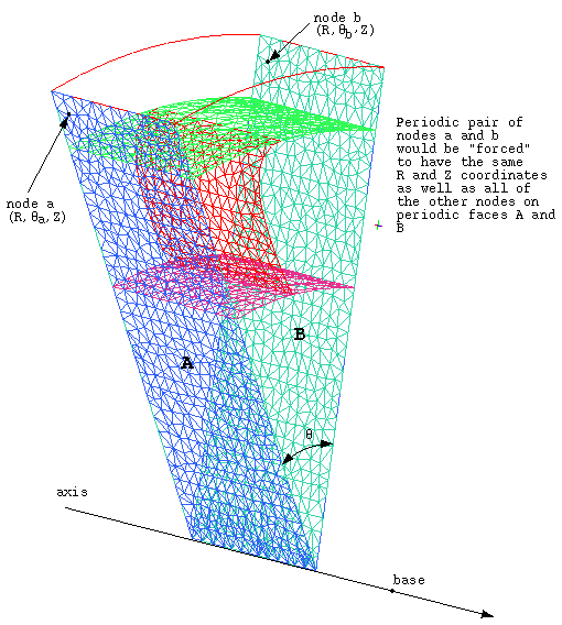
This option ensures that the nodes will line up along an axis symmetric model, and also force the nodes to be rotationally periodic with one another. An example of rotational periodicity is that a node and its periodic counterpart on an opposing periodic face share the same R and Z coordinates of a cylindrical coordinate system. Ansys ICEM CFD has the ability to mesh all the way to the axis of rotation.
There are three methods to defining the Rotational axis.
The User defined methods require the following parameters:
Base
The x-, y-, and z-coordinates of the origin for the axis of rotation. These values are always interpreted in the global coordinate system.
Axis
A vector defining the direction of the axis of rotation (i j k).
Angle
The angle that makes up the computational domain within the axis symmetric model. An angle of 360 degrees would mesh the entire rotational domain.
Note:Angle must be positive value.
The Angle value must divide 360 degrees an integer number of times, with zero remainder.
OR
Sectors
The number of sectors in 360 degrees that make up the entire rotational computational domain.
The Vector method requires 2 points to define the vector for the axis of rotation, and the angle to define the rotational domain.
An example of a rotational periodic mesh is shown in Figure 290: Rotational Periodic Mesh.
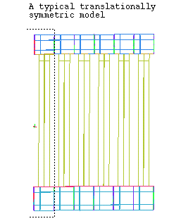
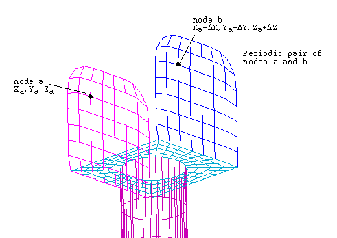
- Translational Periodicity
This option ensures that the nodes line up along a translational symmetric model, as illustrated in Figure 291: Translational Periodic Geometry and Figure 292: Translational Periodic Mesh. Enter the Offset vector value that defines one periodic face from the other (Dx Dy Dz).
- Convert coordinates to global coordinates
allows you to specify the Axis or Offset periodic coordinates in an active local coordinate system (LCS).
Behind the interface, periodicity is always defined in the global coordinate system. When you click this control, the Axis vector (or Offset if translational periodicity) will be normalized and the LCS-based parameters will be converted to global coordinates.
This control is disabled if the Axis (Offset) coordinates are unchanged; or if LCS data is missing or inactive. For more information on working with a LCS, see Local Coordinate Systems
Note:For rotational periodicity, Base parameters (x-, y-, and z-coordinates of the origin for the axis of rotation) are always interpreted in the global coordinate system.
If you click without clicking this button, the Axis or Offset coordinates will be interpreted in the global system without conversion.