- Auto Reduction
In some cases, the prism mesher is unable to create the specified number and size of layers due to geometry constraints. If this option is enabled, the prism mesher will automatically reduce the layer size to meet the required number of layers without creating pyramids or other problems in the mesh.
This is useful for solvers that require complete prism layers with no pyramids. In Figure 283: Example of Auto Reduction, the prism parameters were set for 6 layers. Without Auto Reduction, there will be stair stepping down to 4 layers in the gap. With Auto Reduction enabled, the mesher created 6 layers as specified by automatically reducing the layer size to fit and redistributing the prism layer as appropriate to improve quality.
Note: For Fluent Meshing pre inflation prism growth, if Auto Reduction is set, layer compression is used to avoid invalid mesh in areas of proximity or collision. In these areas, the defined heights and ratios are reduced to ensure the same number of layers throughout the entire prism mesh.
- Blayer 2d
This option is used to create a boundary layer in a 2D mesh using prism meshing. This surface mesh can be used with a 2D solver or swept to create the volume mesh.
Note: Using Prism BLayer 2D is more advanced than applying an Offset with the Patch Independent meshers. Offset is controlled by setting the Height, Ratio and Number of layers parameters on the curves. 2D prism controls are the same as regular prism controls, except you must select the surface part as well as the curve part. 2D Prism can also be applied on an existing shell mesh in the same way that 3D prism is applied to an existing tetra mesh.
Note: Since 2D prisms are really just quads, the split prism and redistribute prism commands do not work.
2D prism works with quad or tri mesh and can be controlled with the 3D prism controls to adjust number of layers, initial height, orthogonality, etc.
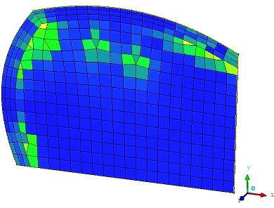
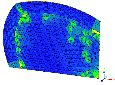
Figure 284: BLayer 2D Applied to a 2D Surface with Quad Mesh shows a 2D surface with quad mesh, with prism applied to the top and left curves.
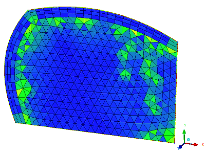
Figure 285: BLayer 2D Applied to a 2D Surface with Tri Mesh shows a 2D surface with tri mesh, with prism applied to the top and left curves. Note that the initial height is "floating" in this case.
Figure 286: BLayer 2D and Additional Prism Parameters Applied to a 2D Surface with Tri Mesh shows the same 2D surface with tri mesh, with prism initial height set to 1, ortho weight set to 0.5, and number of layers set to 7.
- Delete Base Triangles
If enabled, the triangles at the interface with the existing tetra elements will be deleted when growing into ORFN regions.
- Delete Standalone
If enabled, triangles that are not attached to anything will be deleted.
- Do Checks
If enabled, additional checks are done on the mesh. These include checking interfaces between materials and checking for pockets within the mesh. Results are reported in the message window and the prism log file.
- Do Not Allow Sticking
If enabled, "pointy" tetrahedra are not allowed to be stuck between layers.
- Incremental Write
If enabled, after each layer is generated, the prism data will be written into a separate mesh file. The files will be located in your working directory with default file names prism_layer#.uns, and with # incremented for each layer. This can help to isolate and correct problems at a specific layer in the prism mesh.
- Intermediate Write
If enabled, the prism file will be written out after each layer is created. This is a fail safe measure. If the Prism mesher is not able to complete all the layers or is interrupted for some reason, you can load the saved mesh file and continue. The mesh file will be located in your working directory and named "prism.uns".
- Interpolate Heights
if set to On, determines the prism layer heights of prism nodes without given heights by constructing new data points from prism nodes with fixed heights. If there are no fixed heights, the size of the triangle is used. By default, Interpolate Heights is off.
- Refine Prism Boundary
If enabled, this allows the Prism mesher to refine the boundary between the prisms and tetras, if this will improve the mesh quality.
- Stair Step
This option affects the behavior of the Stop Columns option, and is only effective if Stop Columns is enabled.
If Stair Step is enabled, the difference in adjacent prism columns is limited to 1 layer. When disabled, adjacent columns can have different numbers of layers that differ by more than 1.
Note: Stair stepping is enabled by default in Fluent Meshing inflation.
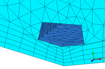
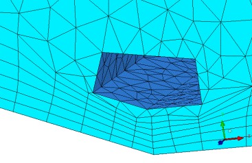
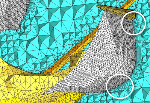
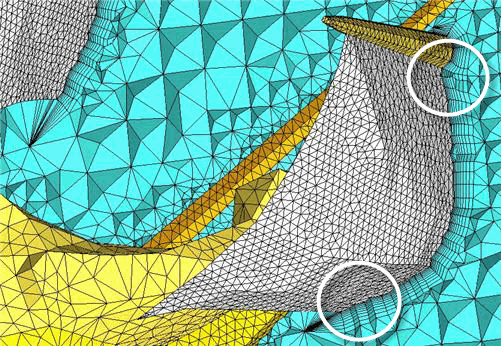
Figure 287: Using the Stair Step Option shows the prism layers grown on a ship sail. The second image shows that when the Stair Step option is disabled, the prism layers are fully extruded on the sail.
- Stop Columns
If enabled, a column of prisms is stopped if the marching direction cannot be determined or a collision is detected. If disabled, and a collision is detected at any point, the entire next layer is stopped unless Auto Reduction is also enabled. In many cases, disabling this option may cause the Prism mesher to terminate prematurely.
Figure 288: Example of Stop Columns and Stair Step Options
Stair Step option enabled: 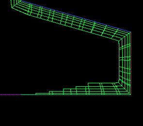
Stair Step option disabled: 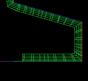
- Use Existing Quad Layers
This option deals with cases where a prism layer meets a wall. If enabled, the software will attempt to align the boundary of the prism layers to the existing quad surface mesh. If the existing mesh has a different structure or the prism mesh has trouble mapping to the structure, then the prism faces will be used for the surface mesh. If disabled, this option will adjust the existing mesh to follow the faces of the uncovered prisms.
- Max Jump Factor
The maximum allowable jump in height between neighboring vertices (default is 5.0). If adjacent prism columns exceed this ratio, the Prism mesher will terminate prematurely and an error message will note that Max Jump Factor was exceeded.
- Max Size Ratio
The maximum allowable size ratio when growing larger prisms into smaller tetra elements (default is 0.0).
- Min Smoothing Steps
The minimum number of marching direction smoothing steps (default is 6). This does not override Max directional smoothing steps, but acts as a lower limit.
- Min Smoothing Val
The marching directions will be smoothed until the quality is above this value (default is 0.1) or the Max directional smoothing steps is reached. If Min Smoothing Val is met, but the Max directional smoothing steps has not been yet reached, smoothing will continue until the number of Min Smoothing Steps have been completed.
- Ratio Max
The maximum height ratio between prisms from one layer to the next.
- Tetra Smooth Limit
The tetra elements will be smoothed until they are above this value (default is 0.3).
- Verbosity Level
Set a value of 0, 1 (default) or 2 to adjust the amount of detail included in the messages output during the prism meshing process.
Verbosity level 2 is typically used only by developers and can slow the prism generation process if there are a significant number of problems in the mesh.
- Read a Prism Parameters File
allows you to select an existing prism parameters file. This will be used to set all the prism parameters, including Advanced Prism Meshing Parameters. These prism parameters files can be shared between projects for consistency and easy setup.


