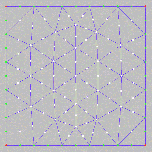
 The Create Mid Side Nodes option allows you to create mid
side nodes on all the elements of the mesh, as shown in Figure 471: Create Mid Side Nodes Example.
- Mid face node
If enabled, nodes will be created at the center of each face.
- Create node on interface
This option is used when creating mid side nodes on the interface between selected elements and the elements attached to them. If enabled, then the edges of the attached elements will also become quadratic. If disabled, then the edges that are common to both the selected elements and attached elements will remain linear.
- Project to geometry
If enabled, the newly created nodes will be projected to the nearest geometry.
- Calculate projection
When a quadratic node is created, it will be projected to all marked curves or surfaces of its linear neighbors, and also the minimum projection will be calculated. The actual projection will be compared to the minimum projection and checked to see if it is within the specified tolerance. If not, the minimum projection will be used.
- Check max
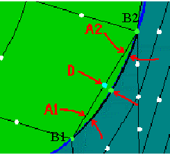
If any of the following three conditions is enabled, then the mid side node that exceeds the required condition(s) will not be projected. For the following max conditions refer to Figure 472: Check Max Conditions.
Check deviation
The distance between the end nodes B1 and B2, multiplied with the value of the Midnode max deviation results in R. Next, imagine a line through mid node D, and perpendicular to line B1-B2. If the position of the projected node falls outside a distance R from the line, then the node will be moved on the geometry so that it falls within this range. If this is not possible, it will not be projected.
Check angle
This refers to the angles (A1 and A2) between the positions of the element edge before and after projection. If projecting a mid node would create an angle above the Midnode max angle, then the mid node will not be projected.
Check chord
The distance between the chord (B1-B2) and the projected mid node is restricted to the specified Max deviation from chord, defined in terms of % of the chord length. If this distance is exceeded then the node will be moved on the line (which is defined by the projected mid node and its projection to the chord) to the position of the maximum deviation.
- Only selected elements
If enabled, you may select the elements to which the operation will be applied.
- Tetra 10 elements
Standard check
If enabled, each projected mid node will be checked for negative values on the determinants at Gaussian integration points of all Tetra 10 elements to which the mid node belongs. If this check fails for at least one element then the dimension of the mid node will be increased. That is, if it was projected to curves it will now be projected to surfaces, and then this check will be done again. Or if the mid node had been projected to surface, it will now be linearized.
Strong check
If enabled, a stronger check with respect to the Tetra 10 elements of the mid node will be done.
- Automatic refinement
This is available only in the case of tetrahedral elements. For all elements a temporary mid node will be created on each element edge (with projection) and it will be checked with respect to some diagnostic criteria for the attached tetrahedrals. If any of the criteria is not fulfilled, the element edge will be refined. In general it is not advisable to use this option.
- Smooth refinement
If enabled, the mesh will be smoothed with 5 iterations to reach an aspect ratio of 0.25 for the tetra elements.


