The display options for Pre-Mesh are shown below.
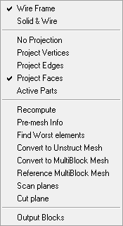
- Wireframe
Displays the model in the wireframe mode.
- Solid
Displays the model in the solid mode.
- No projection
When the mesh is generated, it will conform to the blocking without being projected to the actual CAD geometry.
- Project vertices
When the mesh is generated, the vertices/points on the edges of the blocks will be projected to the curves or surfaces to which they are associated. No other projection will take place.
- Project edges
When the mesh is generated, the nodes on the edges of the blocks will be projected to the curves or surfaces to which they are associated. The face nodes will not be projected to the surfaces, but rather interpolated between the edges. This option is generally used for two-dimensional models. Project edges may be used for three-dimensional models as well, as a method to quickly confirm a correct mesh before employing the Project faces operation.
- Project faces
When the mesh is generated, all face nodes and edge nodes will be projected to their associated curves and surfaces. This option is generally used for three-dimensional models.
- Active Parts
Allows you to select surface parts to be considered for projection when the mesh is generated. All surface parts highlighted in the selection list will be projected to during the mesh generation.
When you compute the pre-mesh, a message will appear indicating the part(s) to which projection has been disabled.
- Recompute
Recomputes the mesh.
- Pre-mesh Info
Reports the number of nodes and elements, by type, in the message window.
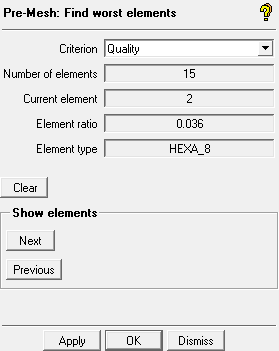
- Find Worst elements
Displays those elements of the pre-mesh that have the worst value of the selected criterion in the graphics window.
- Criterion
Specifies the Criterion for finding the worst elements. For descriptions of the criteria, see Pre Mesh Quality Options.
Select the criterion and click .
The Number of elements, Current element, Element ratio, and Element type are updated automatically. The number of elements and the range are also reported in the message window. The display shows the current worst element, identified by a point in the display.
- Clear
Clears the worst element details.
- Show elements
Enables you to view the elements identified. Click or to step through the identified elements one by one.
Note:The software automatically finds a range of bad elements including the worst element and those near it. The range of elements must be less than 500 elements or the function will be skipped. If only 1 element is found, the / buttons will be greyed out.
This option is disabled if the Pre-Mesh Quality histogram is displayed.
This option is intended for a 3D blocking. If you have a 2D blocking and the selected criterion do not exist, you will get an error message.
- Convert to Unstruct Mesh
Converts the blocking to an unstructured mesh.
- Convert to MultiBlock Mesh
Writes out the multiblock mesh for the current blocking.
- Reference MultiBlock Mesh
Matches node positions of the loaded multiblock mesh to those in the referenced multiblock mesh file in the current directory. By matching the current premesh to a previously smoothed mesh, you can experiment with different smooth mesh options.
Note:Only one multiblock mesh file should exist in the current directory.
The topology of the loaded blocking and the topology of the multiblock mesh must match.
- Scan planes
Scan planes are used to view the volume grid. The following Scan plane control window will be displayed.
There are a number of selection fields for displaying scan planes across each of the principal directions (i, j, k, o3, o4, etc.). #0 corresponds to the first scan plane across i, #1 corresponds to the second, across j, etc. Higher scan planes, such as #3 or #4, scan across the first and second Ogrid indices, respectively.
There is a Block and a Grid index for each scan plane. The Block index is the block number in which the scan plane is displayed. The lowest and highest block are typically in the VORFN region and may not be displayed. The Grid index is the node number within the block.
The up/down arrow buttons allow you to increase/decrease the Block or Grid index by one, respectively. If you click and hold down the up/down arrow button, you will be able to scroll through the Block/Grid index (you need not click the button repeatedly).
By default, the scan plane is in the color of the volume parts it passes through. However, the Color buttons allow you to specify a color for each scan plane (see Figure 146: Selecting the Scan Plane Color).
The Select button allows you to select an edge in the model. The scan plane perpendicular to this edge is then displayed. This is the easiest way to place a scan plane in the model.
The Solid check box controls whether the mesh will be displayed in solid or wire-frame form.
Tip: Scan planes are very useful for diagnosing blocking issues. Running a scan plane through the problem area is often the best way to gain understanding of what is happening in the volume. Typically the scan plane will reveal issues with projection or edge distribution. Fixing these will improve the quality. Enabling the display of edge association and edge bunching can also help identify the problem.
- Cut Planes
A cut plane is used to visualize results on a plane cut through the three dimensional model. Results are viewed on the cut plane as well as on the 2D Dynamic window. The cut plane may be defined in several ways depending on the application.
- Method
By Coefficients
Defines the cut plane by the equation of the normal vector. The equation is of the form: Ax + By + Cz + D = 0. Enter the coefficients A, B, C, D of the equation.
By Point and Normal
pt
Enter the Global Cartesian coordinates in the X, Y, and Z direction.
NX
Enter the X component of a unit vector normal to the desired cut plane.
NY
Enter the Y component of a unit vector normal to the desired cut plane.
NZ
Enter the Z component of a unit vector normal to the desired cut plane.
By Corner Points
Creates a cut plane passing through the given three points. You can enter the Cartesian coordinates of Pt1, Pt2, and Pt3 points.
By 3 Points
You can select any three points in the GUI using the left mouse button to define a cut plane.
Move or Rotate
You can interactively move a previously defined cut plane while holding the left mouse button down. Once you get to the desired location, release the mouse button. Use the middle mouse button to rotate the cut plane about the normal axis. When you get the desired orientation, release the mouse button. To end the interactive movement of the cut plane, click the right mouse.
Middle X plane
This will put the cut plane at the middle of the geometry in the X-direction.
Middle Y plane
This will put the cut plane at the middle of the geometry in the Y-direction.
Middle Z plane
This will put the cut plane at the middle of the geometry in the Z-direction.
- Fraction value
Select the location of the plane by changing the fraction value either by moving the sliding bar or entering a value.
- Solid Mode
To display the cut plane in solid mode.
- Shrink elements
To shrink elements in the display.
Note: Cut planes show the grid lines relative to planes in 3D space. Scan planes show grid lines relative to grid planes. Either method may be used. For unstructured blocking, it is recommended that cut planes be used.
Note: The cut planes for Pre-Mesh can be viewed before writing out the mesh. This allows for mesh quality inspection and block editing before writing out the final mesh.
- Output Blocks
Toggles between Output Block topology and regular blocking topology.
ICEM CFD supports two levels of block decomposition. The first and typical level is what you see by default and what is used to mesh the model. The second level, called Output Blocks, is used to group blocks together resulting a smaller number of meshing files for the solver.
The following tools are used with Output Blocks:
- Init output blocks
Makes your Output Block topology the same as your regular block topology. See Blocking Options.
- Output Blocks
Toggles Output Block topology for block editing and writing of multi-block structured mesh files.
When enabled, you can edit the Output Block topology with operations such as Merge Blocks, Extend Split, Merge Face, and Renumber Blocks. Regular block topology that is used to mesh the model remains unchanged. Merging blocks, for example, can reduce the number of structured mesh files written for the solver.
- Transfer Blocks
Allows you to bring blocks from the regular block topology into the Output Blocks. Use this option when you have already completed most of the output blocks definition and need to add a regular block(s) to the output blocks. See Transfer Blocks.
Note: Face selection operations for Output Blocks are not fully supported.