Elements can be grouped into Subsets, which have display options that can be controlled independently.
Note: To view the contents of a single subset, select the subset and deselect all other subsets.
Subsets work independently of the active elements under parts and types. You can switch between displaying entities by part, type, or by a defined grouping in a subset. Parts and Subsets are Boolean with the geometry, but they are not Boolean with each other, meaning, by turning a subset off, it does not turn those entities off unless they are off in the part as well. To access specific entities of geometry, mesh, or blocking, you can place the entities into a subset. By turning off the Parts, and displaying the subset, you can choose to view only the entities in the subset.
Parts are exclusively defined, so that an entity can only be in one part. But one entity can be part of multiple subsets.
Clicking the right mouse button on Subsets in the Mesh Tree will give the options below.
- Create
To create a new subset of active parts and types. There are different options for creating subsets as shown below.
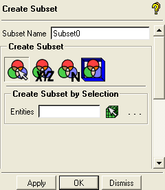
- Create Subset by Selection
 Create a subset by entering a name
and selecting either geometric or mesh entities.
Create a subset by entering a name
and selecting either geometric or mesh entities.- Create Subset near Position
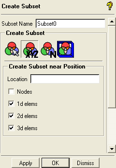
 Create a subset near a certain position
by entering the XYZ coordinates as shown below.
Create a subset near a certain position
by entering the XYZ coordinates as shown below.Nodes
Toggle this ON if nodes are to be selected.
1d elems
Toggle this ON if 1d elements (lines and curves) are to be selected.
2d elems
Toggle this ON if 2d elements (surfaces) are to be selected.
3d elems
Toggle this ON if 3d elements (volumes) are to be selected.
Toggle OFF the options that you do not wish to select.
- Create Subset by Element Number
 Create a subset by entering
the elements numbers of the elements you want to include.
Create a subset by entering
the elements numbers of the elements you want to include.- Create Subset in Region
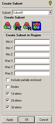
 Create a subset in a specified region
as shown below.
Create a subset in a specified region
as shown below.Min and Max Coordinates
Enter the minimum and maximum coordinates that represents the region.
Include partially enclosed
Includes elements partially enclosed in the region specified by the coordinates.
Nodes
Toggle this ON if nodes are to be selected.
1d elems
Toggle this ON if 1d elements (lines and curves) are to be selected.
2d elems
Toggle this ON if 2d elements (surfaces) are to be selected.
3d elems
Toggle this ON if 3d elements (volumes) are to be selected.
Toggle OFF the options that you do not wish to select.
- Find Worst
Creates a subset of the elements with the worst quality found using the "Quality" criterion.
- Show All
Displays all subsets.
- Hide All
Hides all subsets.
- Shadings
allows you to set the shading for the subset independent of the shading used for the mesh. This allows for better visibility as the subsets can be distinguished from the surrounding mesh. By default, the shading of the subset is Inherited from the shading used for the mesh. You can also select the Wire Frame, Solid, or Solid & Wire rendering.
Note: Subsets created from the Quality Metric Histogram will retain their Color by Quality based color and shading independent of this setting.
Tip:To display other subsets with Color by Quality, combine the Solid or Solid & Wire subset shading with the Color by Quality mesh display option.
To display the elements of a DIAGNOSTIC subset without the Color by Quality shading, you can copy it to a new subset and disable the DIAGNOSTIC subset ().


