


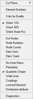
Right-click in the Display tree to see the options available for displaying the mesh, shells or volumes, as shown below.
- Cut Plane
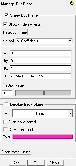
Manage Cut Plane
Opens the Manage Cut Plane DEZ as shown below. This option is described in Mesh Cut Plane in the Main Menu chapter.
Show Cut Plane
If toggled ON, the Cut Plane will be displayed.
- Element Numbers
Displays the numbers of the visible elements.
- Color by Quality
Displays the elements according to the quality color setup. The color contour bar displays the range of colors by quality.
- Shrink 10%
Displays each element shrunk by 10% of its original size.
- Shrink 50%
Displays each element shrunk by 50% of its original size.
- Shrink Node Pos
Works in collaboration with the Shrink features that were previously described to redraw the nodes, depending on whether or not the elements were shrunk.
- Dot Nodes
Displays nodes as dots. If the display background color is dark, the dot nodes will be displayed as white, and if the background color is light, the dot nodes will be displayed as black.
- Node Numbers
Displays the numbers of the visible nodes.
- Node Coords
Displays the coordinates of all the visible nodes.
- Elem Verts
Displays the node order numbers of the visible elements. Works best if a shrink factor is also displayed. The element vertex numbers can help you see how an element is defined, and thereby see the orientation of the element. For example, a tri element is defined by three nodes in a particular order (0, 1, 2). This defines the orientation of the element.
- Elem Triads
Displays the orientation triad of each visible element, with the I, J, and K directions.
- No Inner Elems
Shows only the outer volume elements and hides the inner volume elements.
- Periodicity
Identifies the periodicity of the nodes, either translational or rotational.
Note: Periodicity applies only to Volume (Tetra and Hexa) Meshing, as well as Patch Independent Meshing.
- Quadratic Shape
Displays the correct curvature of edges with midside nodes.
- Wide Lines
Displays wider lines for elements.
- Couplings
Displays couplings. Couplings consists of defined hanging nodes and arbitrary interfaces.
- Locked Elements
Displays any locked elements.
- Distributed attribute
Makes the element with a distributed attribute visible. For example, if a model has distributed boundary conditions, selecting this option allows you to view and edit the BC at an element or node basis. This option is also available as an icon on the Edit Mesh toolbar.
- Diagnostics
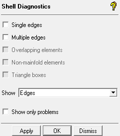
This option allows you to utilize shell mesh diagnostics. The mesh diagnostic options can also be accessed through Edit Mesh > Check Mesh. The difference is that the diagnostic options in the Mesh Display Tree does not add problematic mesh to mesh subsets.
- Single Edges
Displays any single edges of surface mesh elements that are visible. A single edge would represent a hanging edge, and the element would be an internal baffle. These may or may not be legitimate. Legitimate single edges would exist where the geometry has a zero thickness baffle with a free or hanging edge.
- Multiple Edges
Displays any edge that is shared among three or more surface elements. Legitimate multiple edges would be found at a "T" junction, where more than two geometry surfaces meet. These elements are a subset of the single and multiple edge checks.
- Overlapping elements
Displays surface elements that occupy part of the same surface area, but do not have the same nodes. This could be surface mesh that folds on to itself.
- Non-manifold elements
Displays surface elements with non-manifold vertices. Non-manifold vertices are those where the outer edges of their adjacent elements do not form a closed loop. Usually indicates elements that jump from one surface to another, forming a "tent like" structure. This would usually pose no problem for mesh quality but will represent a barrier in the mesh that probably should not be there.
- Triangle boxes
Groups of four triangles that form a tetrahedron with no volume element inside.
- Show
- Edges
Displays only the edges of the surface mesh that are found by the selected diagnostic options. Single edges will be displayed in yellow, and multiple edges in blue.
- Edges and Faces
Displays the edges and one layer of attached faces.
- Edges and 2 layers of Faces
Displays the edges and two layers of attached faces.
- Show only problems
Displays only the elements found by the diagnostic options and turns off the rest of the mesh.