The display options for Shells are shown below.
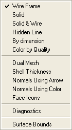
- Wire Frame
Displays the mesh with a wire frame outline, colored part by part.
- Solid
Displays the mesh as a solid mesh.
- Solid & Wire
Displays the mesh as a solid mesh with a wire frame outline. The wire frame is drawn in the color of the background.
- By dimension
Displays shell elements only as solid mesh.
- Hidden Line
Displays a wire frame mesh with the backside of the model hidden.
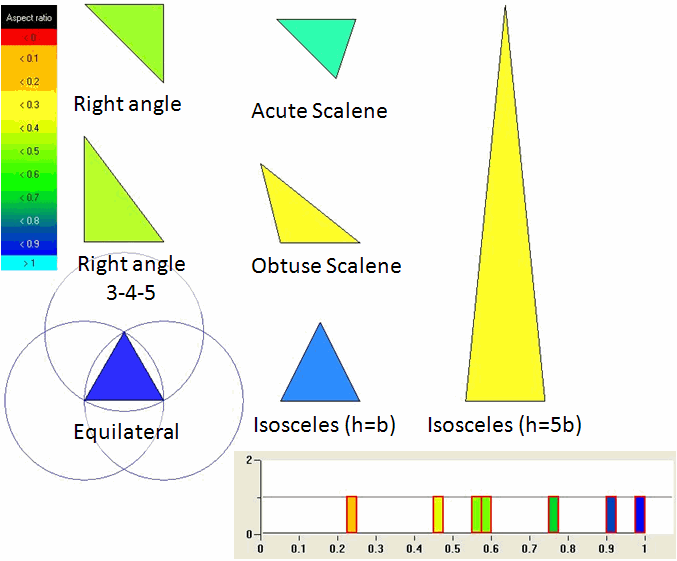
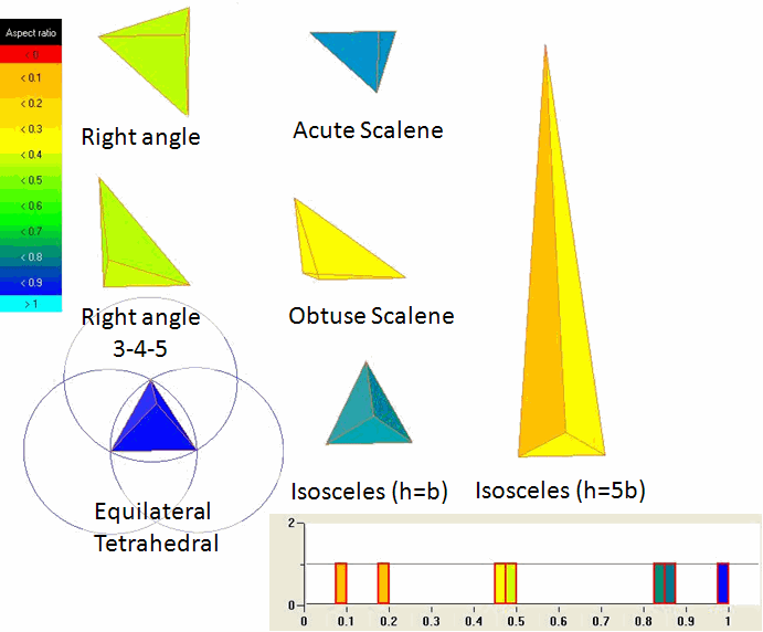
- Color by Quality
Displays the shell elements according to the quality color setup. The color contour bar displays the range of colors by quality.
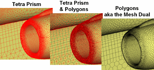
- Dual Mesh
Allows you to view the mesh dual. When enabled, it draws the wire-frame between the centroid of each cell to better show the node centered volumes. An example of the mesh dual for a tetra-prism mesh is shown in Figure 129: Mesh Dual for a Tetra-Prism Mesh.
This option is just a visual aid and can be used only for surface meshes.
Note: The mesh dual of a hexa mesh is still a hexa mesh.
- Shell Thickness
Displays the surface mesh thickness.
- Normals Using Arrow
When enabled, arrows indicating the positive normal direction of each visible unstructured surface element will be displayed.
- Normals Using Color
When enabled, the part color is used to indicate the positive normal side of each visible unstructured surface element. The reverse side of each element is a darker color.
Note: This option works only with Solid or Solid & Wire display.
- Face Icons
Adds part colored face icons to the wireframe display. The icons appear similar to Shrink 75%.
- Diagnostics
This option allows you to utilize shell mesh diagnostics. The mesh diagnostic options can also be accessed through Edit Mesh > Check Mesh. The difference is that the diagnostic options in the Mesh Display Tree does not add problematic mesh to mesh subsets.
- Single Edges
Displays any single edges of surface mesh elements that are visible. A single edge would represent a hanging edge, and the element would be an internal baffle. These may or may not be legitimate. Legitimate single edges would exist where the geometry has a zero thickness baffle with a free or hanging edge.
- Multiple Edges
Displays any edge that is shared among three or more surface elements. Legitimate multiple edges would be found at a "T" junction, where more than two geometry surfaces meet. These elements are a subset of the single and multiple edge checks.
- Overlapping elements
Displays surface elements that occupy part of the same surface area, but do not have the same nodes. This could be surface mesh that folds on to itself.
- Non-manifold elements
Displays surface elements with non-manifold vertices. Non-manifold vertices are those where the outer edges of their adjacent elements do not form a closed loop. Usually indicates elements that jump from one surface to another, forming a "tent like" structure. This would usually pose no problem for mesh quality but will represent a barrier in the mesh that probably should not be there.
- Triangle boxes
Groups of four triangles that form a tetrahedron with no volume element inside.
- Show
- Edges
Displays only the edges of the surface mesh that are found by the selected diagnostic options. Single edges will be displayed in yellow, and multiple edges in blue.
- Edges and Faces
Displays the edges and one layer of attached faces.
- Edges and 2 layers of Faces
Displays the edges and two layers of attached faces.
- Show only problems
Displays only the elements found by the diagnostic options and turns off the rest of the mesh.
- Surface Bounds
Displays the surface boundary region and all elements attached to that region. Useful in visualizing curve boundary regions.