


A cut plane is used to visualize results on a plane cut through the three dimensional model. Results are viewed on the cut plane as well as on the 2D Dynamic window. The cut plane may be defined in several ways depending on the application. These options are described here in detail.
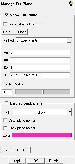
- Show Cut Plane
enables the display of the cut plane.
- Show whole elements
If enabled (default), the cut plane is shown as complete elements. If disabled, the cut plane is shown as a zero-thickness slice.
- Reset Cut Plane
recalculates the extent of the visible mesh and recreates the cut plane. Use this button to ensure the cut plane can be swept through the entire visible mesh if part visibility is enabled or disabled when the cut plane is active.
- Method
contains options for defining the cut plane.
- By Coefficients
defines the cut plane by the equation of the normal vector. The equation is of the form: Ax + By + Cz + D = 0. Specify the coefficients A, B, C, and D in the fields Ax , By, Bz, and D.
- By Point and Normal
defines the cut plane by a point and the normal. Specify the Global Cartesian coordinates in the X, Y, and Z direction for the point (Pn ) and the X, Y, and Z components of a unit vector normal to the desired cut plane (NX, NY, and NZ).
- By Corner Points
creates a cut plane passing through the three specified points. You can enter the Cartesian coordinates for Pt1, Pt2, and Pt3.
- By 3 Points
creates a cut plane passing through the three locations selected.
- Move or Rotate
allows you to interactively move and/or rotate a previously defined cut plane. Use the left mouse button to rotate the cut plane about the normal axis and the middle mouse button to move the cut plane. Click the right mouse button to end the interactive movement of the cut plane.
- Middle X plane
positions the cut plane at the middle of the geometry in the X-direction.
- Middle Y plane
positions the cut plane at the middle of the geometry in the Y-direction.
- Middle Z plane
positions the cut plane at the middle of the geometry in the Z-direction.
- Fraction Value
specifies the location of the plane.
- Display back plane
enables the display of the back plane.
- Draw plane normal
enables the display of the normal direction of the plane.
- Draw plane border
enables the display of the border of the back plane.
- Color
specifies the color of the back plane. To select a different color, click the color bar and select a color from the menu that appears.
- Create mesh subset
creates a mesh subset of cut plane elements.