Utilities for taking measurements of your project’s features or defining a Local Coordinate system are available along with Undo and Redo.
- Measurement Menu
The Measurement drop-down menu contains options to measure distance or angle, or to find the xyz coordinates of a location in the graphical display:
- Measure Distance
 To measure the distance between two points in the graphical display, use the Measure Distance option. Select the locations with the left mouse button. The distance between the two points will be displayed in the message window.
- Measure Angle
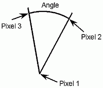
 To measure the angle between two intersecting vectors, use the Measure Angle option. Select three points in the graphical display. The first location is at the point of intersection, and the second and third locations define the two different vectors as shown in Figure 83: Pixel Sequence to Measure Angle. The angle between these two vectors will be reported in the message window.
- Find Location
 To find the xyz coordinates of a point in the graphical display, use the Find Location option. Select a pixel with the left mouse button. The location of the point in space will be displayed in the message window and in the GUI.
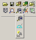
- Local Coordinate Systems
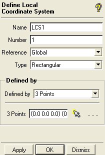
 You can define local coordinate systems (LCS) for use in geometry, mesh, blocking or boundary condition manipulation. The default coordinate system located at the origin is called Global.
 Note: LCS information is saved in both geometry (
.tin) and parameter (.par) files. If the geometry is closed, the LCS data will also be closed if only the geometry was loaded. However, if mesh, blocking, boundary conditions, or loads are also loaded, the LCS data will not be removed when the geometry is closed and/or replaced. This will ensure that the LCS info remains in the case that other entities such as mesh, blocking, boundary conditions, or loads are defined in relation to the LCS.- Name
specifies the name for the local coordinate system (LCS). You can define as many systems as you wish.
- Number
is used by output interfaces to signify a solver's LCS number.
- Reference
specifies the reference coordinate system which is the basis for the new coordinate system.
- Type
specifies the coordinate system type. The LCS Type can be Rectangular (Cartesian), Cylindrical, or Spherical. A Rectangular LCS has X, Y, and Z axes. A Cylindrical LCS has R, θ, and Z coordinates. A Spherical LCS has R, θ, and Φ coordinates.
- Defined by
specifies the method used to define the LCS. The following methods are available:
- Defined by 3 points
In this method, the first point defines the origin of the LCS. The second point defines the positive Z axis relative to the origin for rectangular and cylindrical coordinate systems, and the θ axis (Φ = 0) for spherical coordinate systems. The third point defines positive X for Cartesian coordinate systems, and θ = 0 for cylindrical and spherical coordinate systems. This vector is ortho-normalized if the selected third point is not 90 degrees relative to the first two. Points can be selected by clicking on a graphic location, or by clicking on a prescribed (pre-existing) point.
- Defined by 1 point
The current screen view plane defines the orientation. The selected point defines the origin. The vector normal out of the screen defines the positive Z axis (Cartesian and cylindrical) or Φ = 0 (spherical). The horizontal direction to the right defines the positive X axis (Cartesian) or θ = 0 (cylindrical and spherical). The vertical direction upward describes the positive Y axis (Cartesian) or θ = 90 (cylindrical and spherical). Points can be selected by clicking on a graphic location, or by clicking on a prescribed (pre-existing) point.
Click to create and activate the LCS. A triad showing the coordinate system axes will be displayed in the screen at the point of origin. The Global coordinate system is always displayed in the lower right hand corner (not at the origin). The defined LCS will also appear in the Display Tree.
For more information on options to modify Local Coordinate Systems using the Display Tree, see Display Tree > Local Coordinate Systems.
- Refresh / Recompute

The Refresh/Recompute drop-down menu contains two options:
- Refresh
 The Refresh option allows you to refresh the screen. Use this option to unfreeze the screen after a failed selection or other failed operation.
- Recompute Premesh
 The Recompute Premesh option allows you to recompute the mesh.
- Undo
 The Undo option reverses (undoes) the most recently performed operation.
- Redo
 The Redo option repeats the previously reversed operation.