


 The Edge Params option allows you to modify the mesh parameters in a detailed manner by specifying various bunching laws and the node spacing along any particular edge. Each edge has several parameters that determine the spacing of the mesh along the edge: number of nodes, the meshing law, initial length at the beginning/end of the edge, the expansion of the mesh from the beginning/end of the edge to the interior, and the maximum element length along the edge.
The Edge Params icon brings up a window with all the mesh parameters. Once an edge has been selected, the mesh parameters for that edge will be displayed. All parameter values may be modified, except for the Edge ID and the Edge Length, which are pre-defined.
Note:
You can also parameterize edge parameters using variables in replay scripts. Refer to Parameterizing Edge Parameters for details.
In blocking topologies that include hidden vertices, the reported vertex numbers may not match the visible vertex numbers. See Vertices and Edges.
- Nodes
specifies the number of nodes along the edge. The number may be modified using the up and down arrows or by entering a number in the field.
- Mesh law
Allows you to select one of several bunching laws described in detail in Bunching Laws.
- Spacing
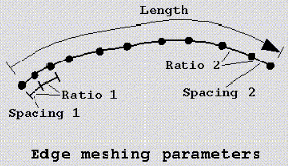
specifies the spacing of the first node from the beginning of the edge (first cell height). When an edge is selected, an arrow appears along the edge. Spacing 1 refers to the parameters at the beginning end of the arrow, and Spacing 2 refers to the edge end where the arrow is pointing, as shown in Figure 399: Edge Meshing Parameters. You may modify the values of the parameters available for the selected Meshing law. The actual values will differ from the requested values only if the requested values cannot be met. For example, if the Edge length is 10 units, and you specify an initial spacing of 6 on both sides and 11 nodes along the edge, the system will simply space the nodes evenly, giving an initial spacing of 1 and a spacing ratio of 1.
- Ratio
is the growth rate from one cell height to the next. Ratio 1 refers to the parameters at the beginning end of the arrow, and Ratio 2 refers to the edge end where the arrow is pointing, as shown in the figure below.
- Max Space
specifies the maximum element spacing of the curve.
- Spacing Relative
if enabled, the values of Spacing 1 and Spacing 2 are displayed as fractions of the edge length.
- Nodes Locked
if enabled, the number of nodes will be fixed. However, Update All will override this and apply the global parameter values to the mesh.
- Parameters locked
if enabled, the Mesh law parameters will be fixed. However, Update All will override this and apply the global parameter values to the mesh.
- Copy Parameters
allows the bunching on the selected edge to be copied with various options. If the To All Parallel Edges option is selected, the distribution of the current edge will be copied to all parallel edges. Parallel edges are edges that start and end with the same index value. If the To Visible Parallel Edges option is highlighted, the distribution of the current edge will be copied to just the visible parallel edges. By default, the bunching parameters of the parallel edges are based upon the relative lengths of the selected edge and destination edges. The To Selected Edges option allows you to copy edge parameters to selected edges. The From Edge option allows you to copy a node distribution from another edge to the selected edge. The application prompts you to select the source edge from which to copy the node distribution. The Reverse options will copy the node distribution and reverse it during the copy operation.
- Copy Absolute
if enabled, the exact spacing from one edge will be copied to the specified edges, regardless of edge length.
- Linked bunching
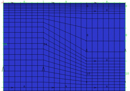
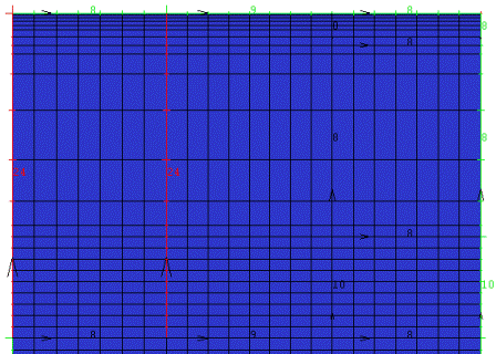
allows the distribution of nodes on a single edge to be identical to the distribution of nodes on a series of smaller, parallel edges. Linked bunching allows you to define a permanent relationship, called links, between these edges. For example, if the node distribution must be modified on the smaller edges, you do not have to specify any node distribution on the larger edge. The node distribution on the larger edge will automatically be updated to reflect the node distribution on the smaller edges. This is primarily used if there are splits that do not cross a block, but mesh distribution on both sides need to match, as shown in the example below.
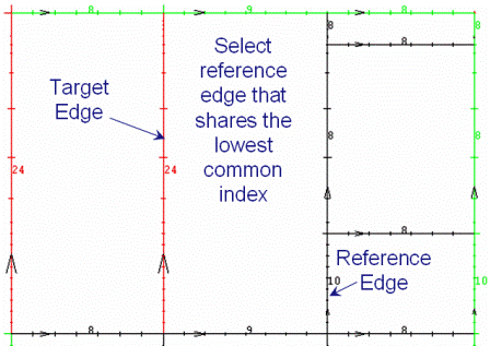
To use this option, first click the select icon for the Edge field (in the Pre-Mesh Params > Edge Params DEZ and select the target edge, which is the longer edge with more nodes. Enable Linked bunching and click the select icon to select the reference edge. It is important to select the parallel edge with the same base index as the target edge. In the example in Figure 400: Linked Bunching Example, the lowest of the three edges is selected because it shares the same base index with the target edge.
Figure 400: Linked Bunching Example
Example of parallel edges with different node distributions
Target and Reference Edge selection
Edges after Linked Bunching option is applied
- Highlight dependent edges
highlights in red the dependent edges of the edge selected.
- Highlight attached faces
highlights the faces attached to the selected edge.
- Highlight Primary edges
highlights in yellow the linked primary edge of the selected edge. Linked edges depend on the primary edge for their parameters.
- Reverse parameters
allows you to reverse the parameters for the ends of the selected edge. The parameters at the beginning of the edge (end 1) are switched with the parameters at the end (end 2).
Note: The number of nodes and the meshing laws specified in the Edge Mesh Parameters always take precedence in determining the number of nodes. Then spacings 1 and 2 are equally balanced, followed by ratios 1 and 2, which are also equally balanced, and finally Max Space is considered.