


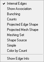
The display options for Edges are shown below.
- Internal edges
To turn the display of internal edges in a volume ON or OFF.
- Show associations
Shows the associations of different edges to curves.
- Bunching
Displays the node distribution on edges.
- Counts
Displays the number of elements of the edges.
- Projected Edge Shape
Displays the edges after mesh calculation with the current node distribution.
- Projected Mesh Shape
Displays the mesh after calculation with the current edge distribution.
- Meshing set
Displays the special meshing sets.
- Shape source
Turns the linked edges ON or OFF. All the arrows will point from the source edge to the target edge.
- Simple
Shows edges in simple form.
- Color by Count
The edge color indicates the number of block faces to which it is connected - yellow means connected to one block face; red means connected to two block faces; blue means connected to three or more block faces.
- Show Edge Info
Gives information about the selected edge. The edge vertices (by number), node spacing, spacing ratio, constraints, edge dimension, index, number of nodes, mesh law, and edge length are reported in the message window.
Note: If the edge includes hidden vertices, the format for vertex display is
Edge (hidden) vertices = n1 (n2) n3. In this situation, you use the first two vertex numbers, n1 and n2, in any blocking command that uses the edge as an input parameter. The command will be applied to the entire edge.