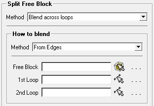
Splits a free block by sweeping a face or by projecting a loop of edges through the free block.
Select a Method using the drop-down list:
- From Faces
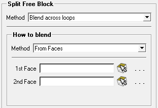
Creates a block by sweeping the selected source face through the free block to the selected target face. The vertices of the source face are projected to their nearest counterpart on the target face.
- 1st Face
Select a source face for the split operation.
- 2nd Face
Select a face to identify a target.
Note: The type of selected faces determines the type of the created block:
If two mapped faces are selected, the result will be a mapped block.
If two free faces are selected, the result will be a swept block.
Mixed selection (free and mapped faces) will generate an error.
An example showing the From Faces option is shown in Figure 359: Use of the From Faces Option.
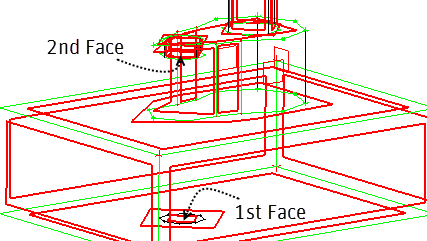
Figure 359: Use of the From Faces Option
(A) The initial 3D blocking shows a single free block. Features extruded from the top surface do not have matching edges on the bottom surface.
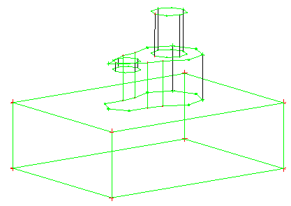
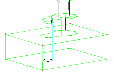
(B) Imprint Face is used to create a free face on the bottom surface, below one of the features.
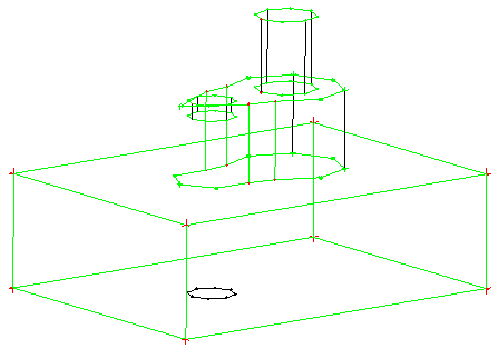
(C) The newly imprinted face is selected as the 1st Face and the corresponding surface near the top of the model is selected as the 2nd Face.
(D) The split block operation creates a new swept block between the two selected faces.
- From Edges
Creates a block by sweeping the selected edges in the first loop to the selected edges in the second loop. Both loops must have the same number of edges.
The order in which the edges are selected is important as a face will be constructed between each pair of edges. That is, a face will be constructed between the first edge on the first loop and the first edge of the second loop, another will be constructed between the second edge of the first loop and the second edge of the second loop, similarly for third edge and so on.
Note: The created side faces are mapped. The type of faces containing the edge loops determines the type of the created block:
If two mapped faces, the result will be a mapped block.
If two free faces, the result will be a swept block.
Mixed (free and mapped) faces will generate an error.
Select the blocking entities using the tools:
- Free Block
Identifies the block to be split.
- 1st Loop
Select edges, in order, to create a source loop. The loop has to be closed. Open loops may be closed using the Imprint Face feature or the Split Free Face feature.
- 2nd Loop
Select edges, in order, to create a target loop.
An example showing the From Edges option is shown in Figure 360: Use of the From Edges Option.
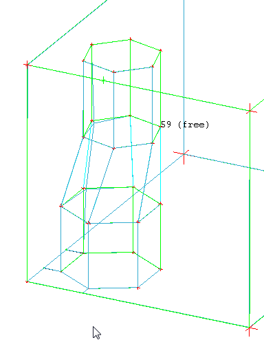
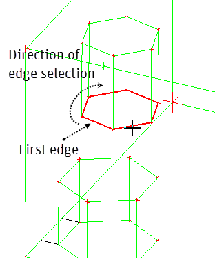
Figure 360: Use of the From Edges Option
(A) The initial 3D blocking shows a single free block with two hexagonal-shaped holes on opposite faces. The holes are not the same size and their edges are not parallel.
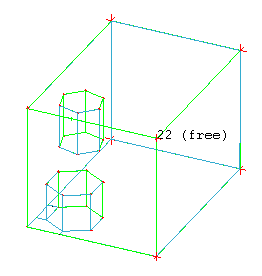
(B) After selecting the free block, the edges of the first loop are selected. Note the start edge and direction of selection.
(C) The edges of the second loop are selected. The first edge and order of selection determine the edge association between first and second loops.
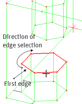
(D) The split operation creates a new free block between the two edge loops.