


The Initial Condition (IC) Table Editor is used to
define spatially varying initial conditions (Specifying Spatially Varying Initial Conditions). It can be accessed from the
Initial Conditions panel or from the library menu
using the  button.
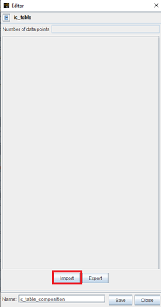
When creating an IC table, you are prompted to import data. Click the Import button at the bottom of the window shown in Figure 2.15: Use Initial Condition Table Editor to create a new table to create a new table. You may import the data using several file formats: a .ftbl file (see Appendix G: File Formats ), a .cgns file (see Appendix G: File Formats), or a generic columnar set of .csv data. Specifically, Ansys Forte solution file (.ftres) which contains spatially-resolved solutions (see Spatially Resolved Panel) is one type of the .cgns files.
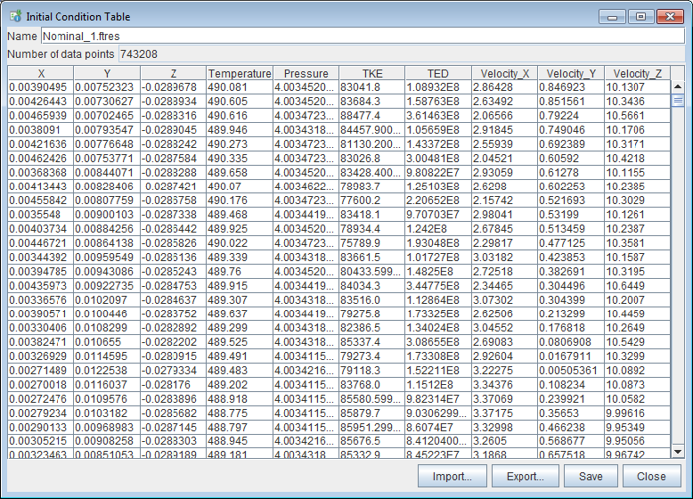
After successfully importing the data, the IC Table Editor displays the set of data imported, including the number of data points and the tabulated data for each variable. It also provides the options to import replacement data from a file source, to export the current table content, to save, or to close the table, as shown in Figure 2.16: Initial Condition Table Editor, populated with spatially resolved data . Note that X, Y, Z coordinate data are required content for initial conditions data.
When you import a .cgns or .ftres file, you have the option to select the needed data from the file. For example, the CGNS-formatted solution files (.ftres) from an Ansys Forte simulation may contain data of multiple variables and multiple solution time points, and you only need select a subset of the variables and one solution time point for the purpose of specifying initial condition. This is done in the interface shown in Figure 2.17: Variable mapping panel, where Ansys Forte variables are mapped to solution variables in an input file.
Figure 2.17: Variable mapping panel, where Ansys Forte variables are mapped to solution variables in an input file
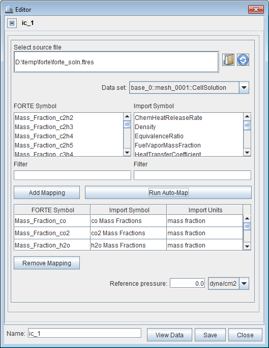
In this interface, there are a group of FORTE Symbols as variables that Forte can read to initialize the corresponding variables, and a group of Import Symbols as variables available from the imported .ftres file. Find a relevant variable from the FORTE Symbol list and its corresponding one in the Import Symbol list and click Add Mapping. You can also click Run Auto-Map to let the software automatically identify the corresponding variables and add the mapping for you.
If the .ftres file contains multiple solution time points, you may choose the needed one from the Data Set list. In this list, you also have the option to select either CellSolution or VertexSolution at each time point. In Forte, scalar variables such as temperature, pressure, species compositions, and turbulence quantities are cell solutions, and vector variables such as velocity are vertex solutions. For the purpose of initializing spatially varying scalar variables, use the CellSolution data set. For the purpose of initializing spatially varying vector variables, use the VertexSolution data set. Be sure to include the X, Y, Z coordinate data to generate the IC table when using both data sets.
If, rather than a .cgns or .ftres file, a .csv, .dat, or .ftbl file is imported, the mapping panel's appearance is identical except that the data set options are absent.
After an IC table is created, be sure to give it a name and save it, before it can be used to specify spatially varying initial conditions (Specifying Spatially Varying Initial Conditions).