


This section describes the recommended settings for a two-stroke engine simulation. Information from the section, Setting Up Generic Engine Cases with Valve Motion Using Automatic Mesh Generation, is also relevant.
This section is arranged in the following parts:
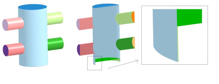
Two-stroke engine geometries require additional attention to set up correctly. The extra complexity arises from the difference in the method used to isolate in-cylinder cells from other portions of the fluid domain. In a valved engine, valve motion explicitly triggers fluid regions in ports to connect or disconnect from the in-cylinder regions. In a typical two-stroke configuration, ports are connected or disconnected from the in-cylinder regions as the piston slides past openings in the cylinder wall. To account for this behavior, the geometry must provide a very tight but non-zero gap between the piston skirt and the cylinder wall. In other words, the piston must fit just inside of the cylinder wall without any edge intersecting the cylinder wall.
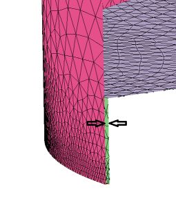
If the gap is too large, columns of cells will be created in the crevice, potentially connecting the ports to the cylinder prematurely. See Figure 4.18: Gap too large.
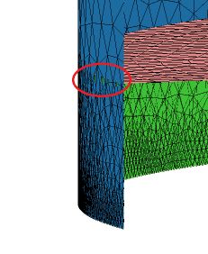
If the gap is so small as to allow piston edges to bleed through the cylinder wall, the surface topology becomes invalid and automatic mesh generation will fail, causing the run to abort. See Figure 4.19: Gap too small.
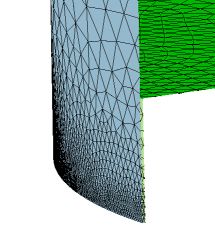
To avoid these issues, the rim of the piston should be resolved at a similar angular resolution as the cylinder wall, and the gap between the piston and cylinder wall should be no more than 0.5% the cylinder bore (ideally < 0.25%). See Figure 4.21: Mismatch in angular resolution causing self-intersections.

Just as with four-stroke valved engines, Forte requires the piston to be at the TDC location with respect to the initial surface mesh state. However, unlike a typical four-stroke setup where the piston "stretches" the liner mesh from TDC to BDC, elongating the cylinder wall as it travels, a two-stroke piston must "squeeze" an existing piston skirt mesh as it travels from TDC to BDC. Since Forte only translates vertices located strictly on the piston, the skirt mesh must be capable of being compressed without causing the surface topology to become invalid. This means the piston skirt should contain no intermediate vertices in the space between BDC and TDC.
Tip: Thus, the easiest way to create piston geometry compatible with two-stroke motion is to generate the surface mesh with the piston in the BDC position and translate the piston to TDC after importing the geometry into Forte.
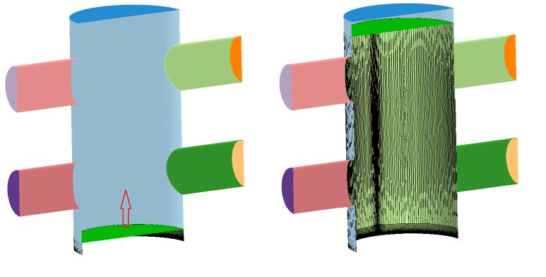
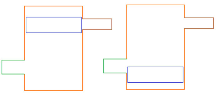
Figure 4.22: BDC position translated to TDC, demonstrates the geometry in the initial configuration on the left, and after translating the piston to TDC on the right. The skirt mesh lines are shown. Note that no intermediate vertices exist between TDC and BDC positions so this skirt mesh can compress without upsetting the topology of the surface mesh.
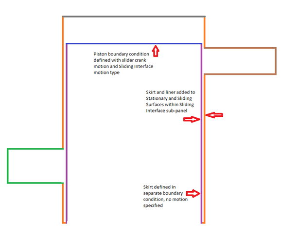
When defining the piston boundary condition, the Motion Type parameter should be set to Sliding Interface. In the subpanel associated with this selection, select the outer cylinder wall and inner wall that define the piston skirt as the stationary and sliding surfaces in the selection control. The piston skirt should be given its own boundary condition separate from the piston, and it should be defined with Wall Motion unchecked.
Pay special attention to the orientation of the surface normals of the piston, skirt, and walls. The direction of normal vectors should be as shown in Figure 4.24: Directions of normal vectors. This image shows the most common topology configuration for two-stroke cases, but other topologies are possible.
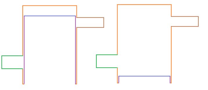
For example, the piston can be defined as a completely enclosed surface anchored at the bottom of the cylinder (with a gap between piston bottom and lower with similar constraints as the skirt-liner gap described previously), with the top of the piston defined as the sole moving surface, as shown in Figure 4.25: Geometry with enclosed piston
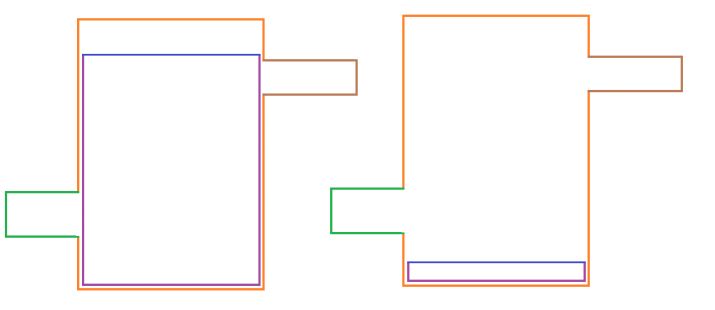
It’s also possible to define an entirely moveable piston, in which case all surfaces are defined as part of the piston boundary condition.
Due to the interaction of the solver time step with the piston skirt and cylinder wall location, the precise timing of when a port opens or closes may vary slightly from cycle to cycle or run to run. This can be minimized by refining the geometry near the port openings. A feature angle refinement control set to ¼ mesh size is often a good choice.